Wednesday, 8 July 2020

Sony HOME AUDIO SYSTEM MHC-V71D disassembly, test modes, SMPS board fault diagnosis

How to disassemble Sony MHC V71 home audio system, test modes, how to take the disc out at emergency, Power board fault diagnosis

US Model, Canadian Model-MHC-V71

AEP Model, UK Model, E Model, Australian Model-MHC-V71D

Destination setting method
The destination information isn’t written in the MOTHERBOARD board for the service.
Therefore, when the MOTHERBOARD board is replaced, be sure to perform the destination setting (Important work).

Note 1: The initial setting destination of the MOTHERBOARD board for the service is temporary set as “LATIN”. The message “LATIN (T)” is displayed on the screen display panel.
Note 2: When distinguishing the destination of the product, refer to the “MODEL IDENTIFICATION”
Note 3: If destination setting isn’t performed, it is possibility to occur the defect to each operation of this unit.
Note 4: Destination would be locked if it has changed for 5 times.

Touch two touch keys of the [FIESTA] and { TUNING + >>| } simultaneously for 10 seconds during the demonstration mode.
2. It enters the destination setting mode, the message "D XXXXX" is displayed on the screen display panel.
Note 5: If the message "DESTLOCK" is displayed on the screen display panel, touch the [>] touch key to release from this mode.
Because the destination is locked, and it cannot change the destination..

3. Touch [ 0+ ] / [ - ] touch key to select the destination based on the set's country.

4. Touch [ > ] touch key to confirm the selection.
5. "RESET" appears on the screen display panel. After that, "SONY “appears on the screen display panel. The system automatically turn on and off once. Please be sure that the system stay at demo mode finally before switch off the power supply.
6. Mode in "MODEL, DESTINATION AND VERSION DISPLAY MODE" again to confirm on the model & destination.


Power output and total harmonic distortion:
(US models only)
With 4 ohm loads, both channels driven, from 400 Hz – 20,000 Hz; rated 60 watts per channel minimum RMS power, with no more than 0.7% total harmonic distortion from 250 milliwatts to rated output.

Speaker section
3-way, Double Bass Reflex Speaker unit:
Tweeter L/R: 50 mm (2 in), cone type
Midrange L/R: 120 mm (4 3/4 in), cone type
Woofer: 300 mm(11 7/8 in), cone type

Supported audio formats
Supported bit rate and sampling frequencies:
MP3:
32/44.1/48 kHz, 32 kbps –
320 kbps (VBR)
AAC:
44.1 kHz, 48 kbps – 320 kbps
(CBR/VBR)
WMA:
44.1 kHz, 48 kbps – 192 kbps
(CBR/VBR)
WAV:
44.1/48 kHz (16 bit)

Supported video formats (V71D)
Xvid:
Video codec: Xvid video
Bit rate: 4.854 Mbps (MAX)
Resolution/Frame rate:
720 × 480, 30 fps
720 × 576, 25 fps (except for Latin American model)
Audio codec: MP3

MPEG4:
File format: MP4 File Format
Video codec: MPEG4 Simple
Profile (AVC is not compatible.)
Bit rate: 4 Mbps
Resolution/Frame rate:
720 × 480, 30 fps
720 × 576, 25 fps (except for Latin
American model)
Audio codec: AAC-LC (HE-AAC is
not compatible.)
DRM: Not compatible.

When disassembling the set, use the following jig (for front panel removal).
Part No.: J-2501-238-A JIG FOR SPEAKER REMOVAL

When the SENSOR board is defective, exchange the SERVICE, TOP PANEL ASSY.

When the MS-476 board is defective, exchange the entire LOADING COMPLETE ASSY (T).

When IC2002 on the MOTHERBOARD board and the complete MOTHERBOARD board are replaced, it is necessary to spread the heat-sink compound between parts and heat sink.

Releasing the disc tray lock
The disc tray lock function for the antitheft of sample disc in the shop is equipped.
It can release the lock function in the following procedure.

Press the [Power] button to turn the power on.
2. Touch the [FUNCTION] touch key to turn the DVD/CD function.
3. Touch [MEGA BASS] and [VOCAL FADER] touch keys simultaneously for three seconds.
4. The message “UNLOCKED” is displayed on the screen display panel and the disc tray is unlocked.
Note: When “LOCKED” is displayed on the screen display panel, the disc tray lock is not released by turning the power on/off with the [Power] button.

IF “PROTECTX” (X IS A NUMBER) AND “CHECK MANUAL” FLASHES ON THE DISPLAY
immediately unplug the AC power cord (mains lead), and check if anything is blocking the ventilation openings of the unit.
After you have checked and found no problems, reconnect the AC power cord (mains lead), and turn on the system. If the issue persists, contact your nearest Sony dealer or the authorized service center.

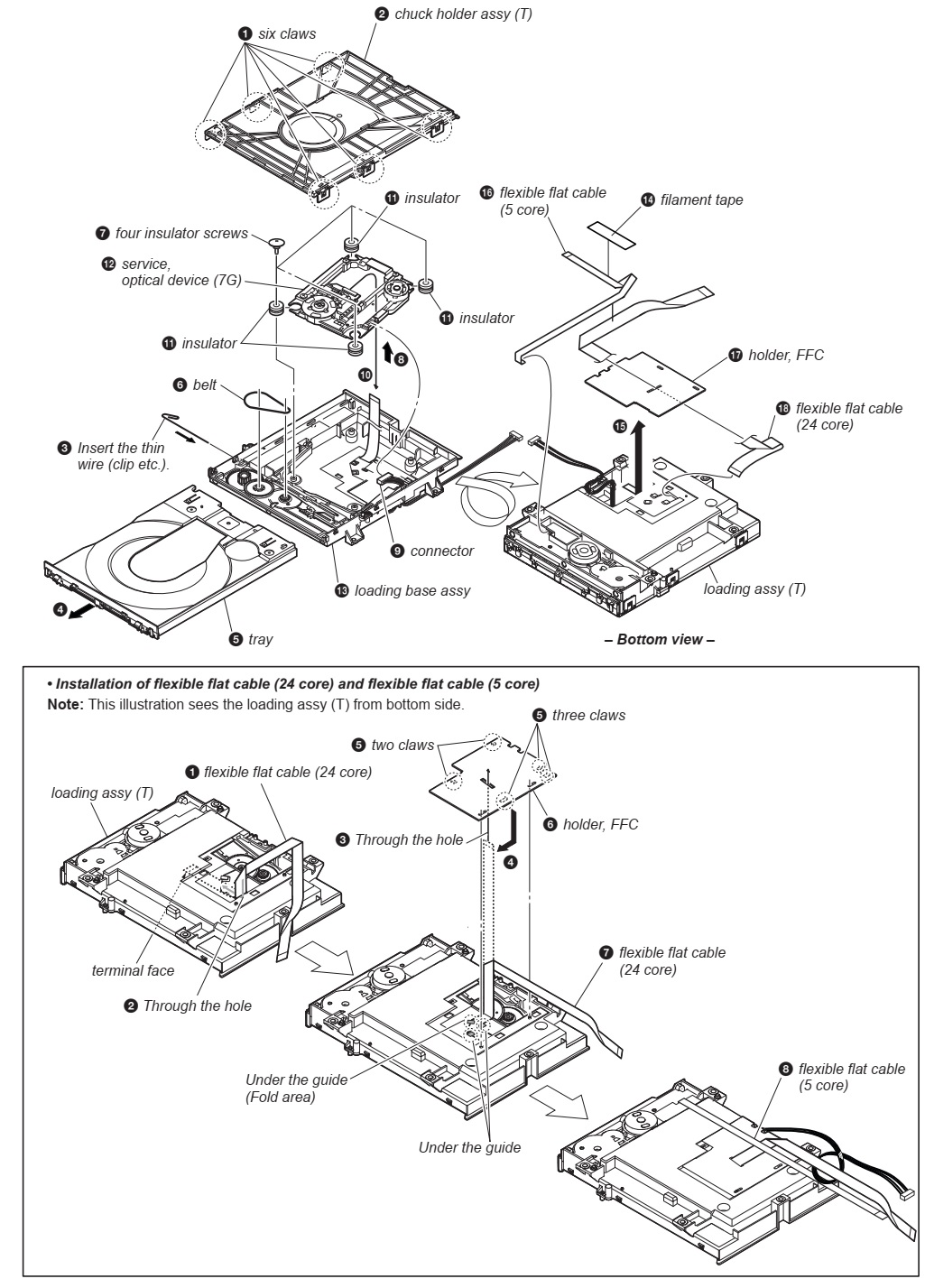
How to open the tray when power switch turn off/ How to take out the disc in emergency
Note 1: After the side panel L, R are removed, this work is done.
Note 2: prepare the thin wire (clip etc. processed to the length of 8 cm or more)

Remove side panel L, R.
Insert the clip etc. processed to the length of 8 cm or more in the hole on the side of the CDM and push. [Refer to the fig below]

Service position

Disassembly procedure of the side panel

Disassembly procedure of loading panel assembly

Disassembly procedure of the top panel [be very careful not to damage any of the flat cables, while tacking the assembly apart]

Rear cover & ventilation cover disassembly

Disassembly of the back panel section

Disassembly of the CDM section

Optical device [7G] & flexible cable service
Dismantling the Motherboard

SMPS/ the power board removal

Front panel [Vanilla] section disassembly

Bottom cover removal

Test modes

Panel test mode
This mode is used to check the screen display panel, LEDs, buttons, touch keys and GESTURE CONTROL sensor.
1. Press [Power] button to turn on the system.
2. Touch [
<] touch key and [MIC/GUITAR LEVEL -] touch key simultaneously for 3 seconds.
3. All LEDs and segments in screen display panel are lighted up.
This is the display check mode.
Touch [ > ] touch key repeatedly to toggle different display mode as below:
Segments on screen display panel:
All On → 1st Group On → 2nd Group On → All On → All Off
Single color LEDs:
All On → All Off → 1st Group On → 2nd Group On → All Off
Multi Color LEDs:
All On → Red → Green → Blue → All Off
4. Touch [0 - ] touch key, the key check mode is activated.
5. In the key check mode, the screen display panel displays “K 0”

Each time a button/touch key is pressed/touched, “K” value increases. However, once a button/touch key has been pressed/touched, it is no longer taken into account. After all the buttons and touch keys have been pressed/touched, “K”
value will toggle between “OK” and “K30”.
The screen display panel displays “<” or “>” or “U” or “u” on the right side of “K30 OK” each time swing left, right, up and down at GESTURE CONTROL.
6. To release from this mode, touch the touch keys in the same manner as step 2, or disconnect the power cord.

Model, destination and version display mode
This mode is used to check the model, destination and software version of the set.
1. Press [Power] button to turn on the system.
2. Touch [
<] touch key and [MIC/GUITAR LEVEL -] touch key simultaneously for 3 seconds.
All segments in screen display panel are lighted up.
3. Touch [ +] touch key. Model information appears on the screen display panel.
4. Touch [ +] touch key. Destination information appears on the screen display panel.
5. Touch [ +] touch key. Serial number appears on the screen display panel.
6. During serial number appears, touch [0 +] touch key. Each time [ +] touch key is touched, the screen display panel shows the version of each category software in the following sequence: SC, MTK, BT, BTE, PF, SUB and return back to
model information display.
7. Touch [
<] touch key and [MIC/GUITAR LEVEL -] touch key simultaneously for 3 seconds to exit.

User reset
The user reset clears all data including preset data stored in the data flash to initial conditions.
1. Press [Power] button to turn on the system.
2. Touch [GUITAR] touch key and [MEGA BASS] touch key simultaneously for 3 seconds.
3. “RESET” appears on the screen display panel. After that, the screen display panel becomes blank for a while, and the system goes to demo mode.

Cold reset
This mode is used to reset all the user settings to factory setting.
Execute this mode when returning the set to the customer.
1. Press [Power] button to turn on the system.
2. Touch [
<] touch key and [MIC/GUITAR LEVEL +] touch key simultaneously for 3 seconds.
3. “COLD RST” appears on the screen display panel. After that, “SONY DEMO” appears on the screen display panel. The system automatically turn on and off once. Please be sure that the system stays at demo mode finally before switch off the power supply.

Disc tray lock
When the disc tray does not open and “LOCKED” appears on the screen display panel, disc tray lock mode has been activated by the shop front.
To release from Disc Tray Lock Mode:
1. Press [Power] button to turn on the system.
2. Touch [FUNCTION] touch key repeatedly to select the DVD/CD function.
3. Touch [MEGA BASS] touch key and [VOCAL FADER] touch key simultaneously and hold down until “UNLOCKED” displayed on the screen display panel.

Shop front demo
The playback started automatically and the “ * DEMO * ” appears on the screen display panel.
This is the Shop Front Demo mode which is activated by the shop front.

Release from Shop Front Demo
1. Touch [
<] touch key and [MIC ECHO] touch key simultaneously for 5 seconds.
2. The message "STANDBY" appears on screen display panel.  After that, the screen display panel blinks for a few times and the system goes to demo mode.

SMPS board and fault diagnosis


Friday, 3 July 2020

How to disassemble Samsung HT H5500, HT H4500 – Home Theater System SMPS, Power board schematic

Power board [SMPS] schematic of Samsung HT H5500w, HT H4500, disassembly procedure

* Never defeat any of the B+ voltage interlocks.  Do not apply AC power to the unit (or any of its assemblies) unless all solid-state heat sinks are correctly installed.

* Do not remove a replacement ESD from its protective package until you are ready to install it.
Most replacement ESDs are packaged with leads that are electrically shorted together by conductive foam, aluminum foil or other conductive materials.

Disassembly and reassembly

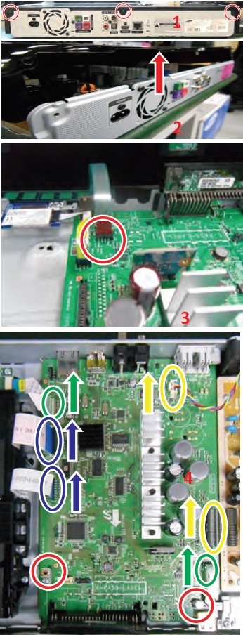
1. Unfasten 3 screws on the back. . BH,+,B,M3,L10,ZPC(BLK),SWRCH18A2

2. Lift the top cover.

3. Disconnect the FCC cable from Touch Key.

Disconnect 2 FFC cables between the Deck and Main.(blue)

Disconnect Fan Wire and SMPS Connector from the Main. (yellow)
4. Disconnect the RX Module from the Main.(green). Unfasten 2 screws on the MAIN PCB. BH,+,B,M3,L6,ZPC(WHT),SWRCH18A

5. Unfasten 3 screws on the back side.
BH,+,B,M3,L10,ZPC(BLK),SWRCH18A

6. Disassemble and lift the main board.

7. Unfasten the Assy-BT by pulling the Assy-BTup.(refer toi mage).  RemovetheAssy-BT.

8. Unfasten 2 screws on the DECK.
BH,+,B,M3,L6,ZPC(WHT),SWRCH18A
And push the locking points on the side.(refer to image)
Remove the Assy-DECK.

9. Unfasten 5 screws on the SMPS. :BH,+,B,M3,L6,ZPC(WHT),SWRCH18A

10. Unfasten 3 screws on the back side.  :BH,+,B,M3,L10,ZPC(BLK),SWRCH18A.  Remove the SMPS and FAN.

11. Unfasten 1screw on the Wireless RX module. :BH,+,B,M3,L6,ZPC(WHT),SWRCH18A.  Romove the Wireless RX module.

12. Unfasten 1screw on the Wi-Fi module.  :BH,+,B,M3,L10,ZPC(BLK),SWRCH18A.  Remove the Wi-Fi module.

SMPS (Power Board) schematic - Samsung [HTH4500]

SMPS (Power Board) Schematics - Samsung [HTH5500w]

Tuesday, 18 February 2020

Sony LCD digital color TV - KDL-46HX900, KDL-46HX900 KDL-52HX900- Service mode, error codes, service adjustments


KDL-46HX900- Hong Kong, KDL-52HX900 & KDL-46HX900-Australia- Remote control RM-GD012 - Error codes and details, how to enter the service mode, Service adjustments
The units  contain a self-diagnostic function. If an error occurs, the STANDBY LED will automatically begin to flash.
The number of times the LED flashes translates to a probable source of the problem.
A definition of the STANDBY LED flash indicators is listed in the instruction manual for the user’s knowledge and reference.
If an error symptom cannot be reproduced, the remote commander can be used to review the failure occurrence data stored in memory to reveal past problems and how often these problems occur.
Diagnostic test indicators
When an error occurs, the STANDBY LED will flash a set number.
of times to indicate the possible cause of the problem.
If there is more than one error, the LED will identify the first of the problem areas.
Result for all of the following diagnostic items are displayed on screen.
If the screen displays a “0”, no error has occurred.
self-diagnostic screen display
For errors with symptoms such as “power sometimes shuts off” or “screen sometimes goes out” that cannot be confirmed, it is possible to bring up past occurrences of failure for confirmation on the screen:
to bring up screen test
In standby mode, press buttons on the remote commander sequentially in rapid succession as shown below:
Since the diagnostic results displayed on the screen are not automatically cleared, always check the self-diagnostic screen.
After you have completed the repairs, clear the result display to “0”.
Clearing the Self Check Diagnostic List
Error history and Error count: Press the Channel 8 => Channel 0
Panel operation time: Press the Channel 7 > Channel 0.
Exiting the Self-diagnostic screen
Turn off the power to the TV by pressing the POWER button on the remote or the POWER button on the TV
How to entering service mode
1) Turn on the main power switch to place this set in standby mode.
2) Press the buttons on the remote commander as follows, and entering service mode.
Service mode display.
Note: First of all, when you enter Service Mode, you can see “Digital” service mode.
Whenever you press “OPTIONS” or “JUMP” on remote, each service mode is changed. “Digital”> “Chassis”> “Sub” > “PEM”
How to use the remote commander in Service Mode
After entering service mode, then turn off the power switch.
White balance adjustment
Execute this adjustment if necessary.
Change Data of “PEM” service mode.
a. Select
“010 WB_GAIN2_A categories by pressing “2 or 5” on remote.
b. Select “000” ~ “005” item by pressing “1or4” on remote.
c. Change data “0 ~ 255” by pressing “3 / 6” on remote.
d. Press “0” or “10” to save data.
It shows red “
WRITE”. 
It indicates writing is processing.
Writing process is done after a while. (Takes about a couple of seconds)
Save changing data
1) Change Data of “Chassis” or “Sub” or “PEM” service mode
2) Write data for “Chassis” or “Sub” or “PEM” service mode
a. Press “Mute” on remote.
It shows green “
SERVICE” changes to green “WRITE”.
b. Press “0” or “enter” on remote. Green “
WRITE” changes to red “WRITE”. It indicates writing is processing.
c. After a while, red “
WRITE” changes to green “SERVICE”. Writing process is done at this point.
3) TV reboot is necessary for applying data change.
Change data
Note: “Digital” service mode don’t have to Save. (Except “002 MODEL” category)
1) Change Data of “Digital” service mode. (
Except “003 DIG_SRV_MODE” category)
a. Press “2 / 5” on remote to select (up / down) category.
b. Press “1 / 4” on remote to select (up / down) Item.
c. Press “0 / 10” on remote to select item.
Change Data of “Digital” service mode. ( “003 DIG_SRV_MODE” category)
“003 DIG_SRV_MODE” is one category of “Digital” service mode.
Please note because this operation is special.
a. Press “2 / 5” on remote to select “003 DIG_SRV_MODE”.
b. Press “1 / 4” on remote to select (up / down) Item.
c. Press “0 / 10” on remote to select item.
d. Press number key “1”~”9” directly. “*” stamp move.
e. Press “12 / enter / select” to decide and advance next step. Press “return”, when returning on the previous page
Write data for “Digital” service mode. ( “002 MODEL” category)
Note: This procedure operation, when replaced the B board.
Note: Do not write a wrong segment or destination information in Product ID.
When the wrong setting is written, TV may not operate.
000 SEG ・・・ Product ID - segment information.
001 DEST
・・・ Product ID – destination information.
a. Change data for each model.
b. Press “0” or “enter” on remote.
It shows red “
WRITE”. It indicates writing is processing.
c. Writing process is done at this point.
Set to shipping condition
How to do shipping condition.
a. Move to “Digital” service mode.
Press “8” on remote.
It shows green “
SERVICE” changes to green “RST-”.
Press “mute” on remote.
Added green “
EXE” after green “RST-” .
d. Press “0” or “enter” on remote. Green “
EXE-RST” changes to red “EXE-RST”. It indicates writing is processing.
After a while, red “
EXE-RST” changes to green “SERVICE”.
And all LED lights.
Writing process is done at this point.
Another way
You can set to shipping condition w/o entering Service Mode.
> “Cursor Up” on remote + “Power Key” on Front panel of the TV.
Change the emitter output level [back-light fault]
Note: To reduce the emitter LED output power strength.
Change Data of “PEM” service mode.
a. Select
“009 3D” category by pressing “2 / 5” on remote.
b. Select “000 EMIT_STR items by pressing “1 / 4” on remote.
c. Change data from “0” to “1” by pressing “3 / 6” on remote.
0: Strong (Default)
1: Weak
d. Save & Reboot.

Wednesday, 12 February 2020

JBL SUB350 Dolby Pro-Logic Surround-Amplifier/Subwoofer Schematic-general troubleshooting - schematic


Used Ics: TLO74, UPC1237HA, IC4558, STK4151, UPC1298V
200 watts
Front channels – 35 watts x 3 @ .1% THD
Surround channels – 15 watts x 2 @.1% THD
Subwoofer – 65 watts @ .1% THD
If there is no sound from any of the speakers, check the following
• Make sure the subwoofer is plugged into an active AC wall outlet.
• Make sure the Master Power Switch, located on the rear of the subwoofer, is in the “On/Standby” position.
• Make sure there is a source – for example, a VCR or television – hooked up to the TV or tape/aux input jacks on The Source.
• Make sure that the program material is playing.
• Recheck the hookup connections.
If most of the sound comes from the center-channel speaker, with little or no information from the surround channels, note the following:
Although most of today’s televisions are equipped with stereo audio output jacks, some stereo televisions have poor audio sections and are unable to provide a Dolby Pro Logic encoded signal. In the unlikely event that you experience this problem, connecting the audio outputs from your hi-fi VCR, laser disc player, DVD player, or satellite receiver directly to one of the inputs on The Source will provide a proper audio signal and allow you to enjoy true Dolby Pro Logic surround sound.
If there is no sound from the surround speakers or sound is very low, check the following:
• Check all connections between the amplifier and each of the speakers.
• Raise the surround volume from the remote control
• Make sure the TV show or movie you are watching is recorded in Dolby Surround.
If there is no sound from the center speaker, check the following:
• Make sure that the processor is in the Pro Logic mode. If it is in Phantom or Stereo mode, the center speaker will not play.
• Check the connections between the subwoofer and the center speaker.
If you have low bass output, check the following:
• Experiment with placement of the subwoofer. Remember, place the subwoofer in a corner to get maximum bass output from the system.
• Increase the level of bass, using the remote control.
• Adjust the level control on the rear of the subwoofer.
If you are having trouble picking up radio stations, check the following:
• Make sure the antenna is hooked up properly.
• Depending on your distance from the station’s transmitter, you may need to install an FM antenna on the roof or in the attic.
Schematic [Circuit diagram]

Thursday, 6 February 2020

Philips AH325 Amplificador schematic - tuner amplifier

Using BD333, BD334 Power transistors [dual]
Level meter schematic
Main schematic
Wiring diagram

Thursday, 30 January 2020

How to enter the service mode - Vestel 17MB230 IDTV – used in Vestel, Regal, Finlux, Telefunken and many other brand LCD TVs


17MB230 main board is driven by Novatek SOC. This IC is a single chip iDTV solution which compliants with variety ATV as NTSC, PAL and SECAM, and DTV standards as ISDB-T, DVB-T/-T2/-C/-S/-S2/-S2X, ITU-T J.83B, 8VSB, DTMB, integrates DTV and multi-media AV decoder, SIF demodulator, and support A/V post-processing
SERVICE MENU SETTINGS
In order to reach service menu, first Press “MENU” button, then write “4725” by using remote controller.  
You can see the service menu main screen. 
You can check SW releases by using this menu. In addition, you can make changes on video, audio etc. by using video settings, audio settings titles.
T/T2/C/A TUNER (U1)
The MxL661 is a highly integrated low-power silicon tuner IC that targets all global and digital cable standards. Broadband input filtering and channel filtering have been completely integrated on-chip. This integration enables a compact design resulting in small footprint, low Bill-Of-Material (BOM) cost, and low-power consumption.
A signal at the 75ohm RF input is filtered and converted to a programmable IF output frequency. Automatic Gain Control (AGC), LO generation, and channel selectivity functions are completey integrated on the chip. All functions of the IC can be controlled using the I2C interface.  The MxL is available in a 4 mm x 4mm x 0.85mm3, 24-pin QFN package.
• Tuning range from 44MHz to 1002MHz
• Programmable channel bandwidths of 6, 7, and 8MHz
• Integrated channel filtering
• Low power consumption with 3.3V and 1.8V dual-supply operation - 351 MW (digital terrestrial)
• On-chip voltage regulator enables single supply 3.3V operation
• Programmable IF frequency and IF spectrum inversion
• Programmable RF to IF delay for ATV scrambling systems that relies on the H-Sync method
• Optional balun-less application note for cost-sensitive applications
• Reference clock output available for re-use by demodulators and additional tuners in multi-channel applications
• Input power reporting
• Open-drain General Purpose Output GPO available for controlling off-chip circuitry
• I2C compatible digital control interface
• RoHS compliance.
S/S2 TUNER (U142)
The AV2018 is a highly integrated silicon tuner for DVB-S2 standard. It integrates a synthesizer, crystal oscillator, LDO, loop through path, and a direct conversion receiver including LNA, RF variable gain amplifiers, Mixer, programmable channel filter, and PGA.  The low noise figure of the receiver and loop through path eliminates the need of an external LNA. The integrated crystal oscillator can provide a reference clock for demodulator. The LDO supplies all the internal blocks the only an external voltage source is required. The AV2018 requires only a small number of external components, thus enables very competitive design.  The AV2018 implements an automatic gain control mechanism that only an analog control signal from the demodulator is required to from a close-loop gain control. The mechanism will arrange the gain of the receiver blocks to achieve best performance according to the control signal voltage. The embedded automatic calibration mechanism provides precise control of channel filter bandwidth and DC offset, no additional calibration procedure is required.
• Input RF Frequency: 950Mhz to 2150Mhz
• Single +3.3V power Supply
• Embedded LNA, Mixer, VCO, crystal oscillator, and LDO
• Low Noise Figure: 5 dB, typical
• Embedded DC offset Cancellation Circuit
• Programmable channel filter with bandwith from 4MHz to 40MHz
• Automatic gain control
• Embedded RF signal loop through path
• Single-ended I/Q interface
• QFN3*3mm 16pin package.
MAIN AMPLIFIER (U9)(6-8-10 W OPTION)
AD82587D is a digital audio amplifier capable of driving a pair of 8 ohm, 20W or a single 4ohm, 40W speaker, both which operate with play music at a 24V supply without external heat-sink or fan requirement.  Using I2C digital control interface, the user can control AD82587D’s input format selection, mute and volume control functions. AD82587D has many built-in protection circuits to safeguard AD82587D from connection errors.
• 16/18/20/24-bit input with I2S, Left-alignment and Right-alignment data format
• PSNR & DR(A-weighting) Loudspeaker: 97dB (PSNR), 105dB (DR) @ 24V
• Multiple sampling frequencies (Fs)
 32kHz / 44.1kHz / 48kHz and
 64kHz / 88.2kHz / 96kHz and
 128kHz/176.4kHz/192kHz
• System clock = 64x, 128x, 256x, 384x, 512x, 768x,1024x Fs
 256x~1024x Fs for 32kHz / 44.1kHz / 48kHz
 128x~512x Fs for 64kHz / 88.2kHz / 96kHz
  64x~256x Fs for 128kHz /176.4kHz/192kHz
• Supply voltage
 3.3V for digital circuit
 10V~26V for loudspeaker driver
• Loudspeaker output power for Stereo@ 24V
 10W x 2ch into 8_ @ 0.16% THD+N
 15W x 2ch into 8_ @ 0.18% THD+N
 20W x 2ch into 8_ @ 0.24% THD+N
• Loudspeaker output power for Mono@ 24V
 20W x 1ch into 4_ @ 0.17% THD+N
 30W x 1ch into 4_ @ 0.2% THD+N
 40W x 1ch into 4_ @ 0.24% THD+N
• Sounds processing including:
 Volume control (+24dB~-103dB, 0.125dB/step)
 Dynamic range control
 Power clipping
 Channel mixing
 User programmed noise gate with hysteresis window
 DC-blocking high-pass filter
• Anti-pop design
• Short circuit and over-temperature protection
• I2C control interface with selectable device address
• Internal PLL
• LV Under-voltage shutdown and HV Under-voltage
• detection
• Power saving mode
• Dynamic temperature control.
SUBWOOFER AMPLIFIER (U8) (12 W)
AD82586C is a digital audio amplifier capable of driving a pair of 8 ohm, 20W operating at 24V supply without external heat-sink or fan requirement with play music.  AD82586C has 20 bands EQ function and can operate 20W stereo or 40W mono optionally.
AD82586C can provide advanced audio processing capabilities, such as volume control, 20 bands speaker EQ, audio mixing, 3D surround and DRC (dynamic range control). These functions are fully programmable via a simple I2C control interface.
Robust protection circuits are provided to protect AD82586C from damage due to accidental erroneous operating condition. AD82586C is more tolerant to noise and PVT (Process, Voltage, and Temperature) variation than the analog Class-AB or Class-D audio amplifier counterpart implemented by analog circuit design. AD82586C is pop free during instantaneous power switch because of its built-in, robust anti-pop circuit.
• 16/18/20/24-bits input with I2S, Left-alignment and Right-alignment data format.
• PSNR & DR (A-weighting) Loudspeaker: 99dB (PSNR), 104dB (DR) @24V. Up
• Multiple sampling frequencies (Fs)
32kHz / 44.1kHz / 48kHz and
64kHz / 88.2kHz / 96kHz and
128kHz / 176.4kHz / 192kHz
• System clock = 64x, 128x, 192x, 256x, 384x, 512x, 576x, 768x, 1024x Fs
64x~1024x Fs for 32kHz / 44.1kHz / 48kHz
64x~512x Fs for 64kHz / 88.2kHz / 96kHz
64x~256x Fs for 128kHz / 176.4kHz / 192kHz
• Supply voltage
3.3V for digital circuit
10V~26V for loudspeaker driver
• Loudspeaker output power at 24V
10W x 2CH into 8 ohm @0.17% THD+N for stereo
20W x 2CH into 8 ohm @0.26% THD+N for stereo
• Sound processing including:
20 bands parametric speaker EQ
Volume control (+24dB~-103dB, 0.125dB/step)
Dynamic Range Control (DRC)
Dual band DRC
Power clipping
3D surround sound
Channel mixing
Noise gate with hysteresis window
Bass/Treble tone control
DC-blocking high-pass filter
• Anti-pop design
• Short circuit and over-temperature protection
• I2C control interface with selectable device address
• Support hardware and software reset
• Internal PLL
• LV Under-Voltage shutdown and HV Under-Voltage detection
• Power saving mode.
HEADPHONE AMPLIFIER (U5)
The AD22657B is a 2-Vrms cap-less stereo line driver. The device is ideal for single supply electronics.  Cap-less design can eliminate output dc-blocking capacitors for better low frequency response and save cost.
The AD22657B is capable of delivering 2-Vrms output into a 10k ohm load with 3.3V supply. The gain settings can be set by users from 1V/V to 10V/V externally. The AD22657B has under voltage protection to prevent POP noise. Build-in shutdown control and de-pop control sequence also help AD22657B to be a pop-less device. The AD22657B is available in a 10-pin MSOP package.
POWER STAGE
Power socket is used for taking voltages which are 12V_stby and 24V (VDD_Audio for 10W option via power_pin1). These voltages are produced in power card. Also socket is used for giving dimming, back-light and stand-by signals with power card.
C1 Module connector details and problems
The TPS54528 is an adaptive on-time D-CAP2™ mode synchronous buck converter. The TPS54528 enables system designers to complete the suite of various end-equipment power bus regulators with a cost effective, low component count, low standby current solution. The main control loop for the TPS54528 uses the D-CAP2™ mode control that provides a fast transient response with no external compensation components. The adaptive on-time control supports seamless transition between PWM mode at higher load conditions and Eco-mode™ operation at light loads. Eco-mode™ allows the TPS54528 to maintain high efficiency during lighter load conditions. The TPS54528 also has a proprietary circuit that enables the device to adopt to both low equivalent series resistance (ESR) output capacitors, such as POSCAP or SP-CAP, and ultra-low ESR ceramic capacitors.
The device operates from 4.5-V to 18-V VIN input. The output voltage can be programmed between 0.76 V and 6.0 V. The device also features an adjustable soft start time. The TPS54528 is available in the 8-pin DDA package, and designed to operate from –40 C to 85 C.
The MP8774 is a fully integrated high-frequency, synchronous, rectified, step-down, switch-mode converter with internal power MOSFETs. The MP8874 offers a very compact solution that achieves 12A of continuous output current with excellent load and line regulation over a wide input range. The MP8774 uses synchronous mode operation for higher efficiency over the output current load range. Constant-on-time (COT) control operation provides very fast transient response, easy loop design, and very tight output regulation. Full protection features include short-circuit protection (SCP), over-current protection (OCP), under-voltage protection (UVP), and thermal shutdown. The MP8774 requires a minimal number of readily available, standard, external components and is available in a space-saving QFN-16 (3mmx3mm) package.
The APL5910 is a 1A ultra low dropout linear regulator. The IC needs two supply voltages, one is a control voltage (VCNTL) for the control circuitry, the other is a main supply voltage (VIN) for power conversion, to reduce power dissipation and provide extremely low dropout voltage. The APL5910 integrates many functions.
A Power-On- Reset (POR) circuit monitors both supply voltages on VCNTL and VIN pins to prevent erroneous operations. The functions of thermal shutdown and current-limit protect the device against thermal and current over-loads. A POK indicates that the output voltage status with a delay time set internally. It can control other converter for power sequence. The APL5910 can be enabled by other power systems. Pulling and holding the EN voltage below 0.4V shuts off the output.
The APL5910 is available in a SOP-8P package which features small size as SOP-8 and an Exposed Pad to reduce the junction-to-case resistance to extend power range of applications.
NOVATEK NT72671TBG MICROCONTROLLER
NT72671TBG is an integrated digital TV system-on-chip which complaints with variety ATV standards (NTSC, PAL and SECAM), and DTV standards (ISDB-T, DVB-T/-T2/-C/-S/-S2/-S2X, ITU-TJ.83B, 8VSB, and DTMB), and integrates DTV and multi-media AV decoder, SIF demodulator, and support A/V post-processing. The integrated video ADC and video decoder support PC VGA port, YPbPr or SCART, CVBS and SCART S-Video Input. The video decoder supports universal TV video format. The integrated audio ADC
supports stereo audio input corresponding to video input sources. The integrated TV sound decoder supports universal TV sound format. The advanced picture quality and color engine create more vivid image impression than ever. The HDMI receiver v2.0 supports deep color, CEC features and 3D input formats. The USB high speed host supports updating firmware code, multi-media playback from the external USB flash devices.
The standby controller can operate solely from the main system, powered by the standby power-source from power module, consumes as low current as possible. It meets the requirement of Green appliance.