Be
sure no power is applied to the chassis or circuit, and observe all other
safety precautions.
Service Mode
With
the TV remote control, enter the following keys in sequence:
[MENU
8 8 9 3]
The
TV screen will display the information as shown below.
In
the last line of the service menu, the card version.
Such
as: "L_MSD209GL_PANEL_MERGE BRA MAY 13 201016.47.31"
Exiting
service mode
Simply
press the EXIT button on the user's remote control or turn the power off.
ATTENTION:
When
performing a software update, memory swapping
If
the EEPROM or the device shows unstable, perform the below:
Press
the UP / DOWN buttons and select Init EEPROM, then press the ">"
button.
seconds
for execution.
NOTE:
After "reset", turn the unit off and on again.
Firmware
Update
This
procedure should only be performed when the equipment is abnormal in its
operation, or when there is an official communiqué to carry out such a
procedure. Do not upgrade if the
equipment is working properly. Carefully
read the entire procedure and perform the task as described below. If in doubt, always seek the help of H-Buster
technical support.
Firmware (software update)
Initial Procedures.
Needed
tools:
-
An empty and formatted pen drive (FAT32) - minimum 512MB;
-
Remote control of equipment;
-
Latest version downloaded from the services website.
To
obtain the latest version, log on to the H-Buster service website and download
as the LCD panel model (if present). If you have any questions, contact
technical support.
How to identify the Panel Type
Service
Mode Menu
Rear
side of LCD Panel
Identification
of the LCD panel by the label attached to the reverse (inner part)
Copying the firmware to USB Memory Key
The
file that is on the services site is "zipped (compressed)." To unzip
it, it is necessary to have a decompress program installed on your computer (eg
Winzip, WinRAR, etc.) Save to the desktop and unzip it to the PC. If the
decompress or program creates open the folder and copy to the pen-drive the
file that is inside the folder (NOT COPY TO ALL PASTE).
The
name of the file to be copied to the pen drive SHOULD NOT BE CHANGED, CASE
CONTRARY TV WILL NOT RECOGNIZE THE FILE
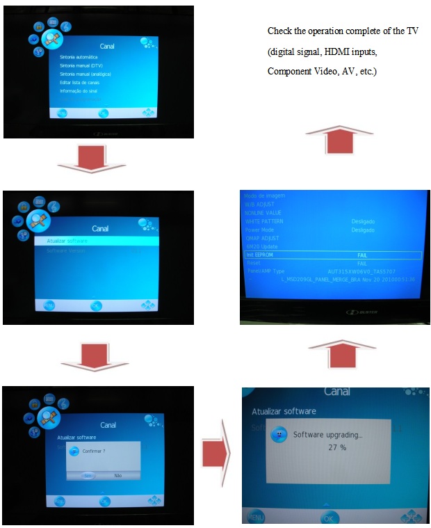
Updating the firmware
Follow
the procedures below carefully:
1)
With the TV working, connect the pen drive with the recorded program to the USB
port;
2)
Press the MENU button on the remote control and go to the CHANNEL option with
the navigation keys and press OK;
3)
In the CHANNEL menu, scroll to the next page where "Update Software"
will appear and press OK;
4)
The confirmation question will appear on the screen, confirm and press OK;
5)
Wait until the end of the update, where the equipment will turn off and restart
itself;
6)
Enter the service menu and reset the memory with the INIT EEPROM command.
Firmware Update Diagram
Check
the operation complete of the TV (digital signal, HDMI inputs, Component Video,
AV, etc.)
Power Supply Board Failure Check.
State:No picture
First,check cables which connect with PSU,then check as follows
Check input voltage
voltage: +5VSB----POWER ON(2.6V) --+12V
State: No sound
First,check cables which connect with PSU,then check as follows
1) Check input voltage as NO picture
2) Check speaker output
check speaker anode(+) and cathode(-), confirm speaker short or not. If any defect found replace the speaker.
Audio output stage schematic
Main board of HBTV-32D02FD / HBTV-40D02FD boards locations.
HBTV-32D02FD
Mainboard-HBTV-32D02FD / HBTV-40D02FD-Connector definition
Power Supply Board-Connector definition: HBTV-32D02FD
HBTV-40D02FD-LED LIPS AC input pin configuration
LCD Panel-Display the signal-Connector
definition-HBTV-32D02FD
HBTV-40D02FD Input signal and power
Note1: No Connection: These PINS are used only for SAMSUNG. (DO NOT CONNECT)
Note2: LVDS OPTION : If this PIN is:
HIGH
(3.3 V) Normal LVDS format
LOW (GND) JEIDA LVDS format
SEQUENCE : On = VDD(T1) LVDS Option Interface Signal(T2)
OFF = Interface Signal(T3) LVDS
Option VDD.