Sunday 23 December 2018

SDR H100P-Panasonic video camera, factory mode, service mode, self check, error codes

Panasonic SD / HDD Video Camera

Model No. SDR-H100P, SDR-H100PC, SDR-H100EB, SDR-H100EC, SDR-H100EE, SDR-H100EF, SDR-H100EG, SDR-H100EP, SDR-H100GT, SDR-H101EB, 
SDR-H101PR, SDR-H101PU, SDR-H101GA, SDR-H101GC, SDR-H101GK, SDR-H101GN

Please do not attempt to disassemble this device, if you don’t have needed tools and sufficient experience. This is not an easily repairable device for a customer. Contact the service centre for Panasonic to get it repaired. No user repairable parts inside.
How to Replace the Lithium Battery
The lithium battery is a critical component.
(Type No.: ML-614S/DN Manufactured by Energy Company, Panasonic Corporation)
It must never be subjected to excessive heat or discharge.
It must therefore only be fitted in equipment designed specifically for its use.
Replacement batteries must be of the same type and manufacture.
They must be fitted in the same manner and location as the original battery, with the correct polarity contacts observed.
Do not attempt to re-charge the old battery or re-use it for any other purpose.
It should be disposed of in waste products destined for burial rather than incineration.
1. Remove the Monitor P.C.B.
2. Unsolder the Lithium Battery "ML-614S/DN" and then replace the new one.
How to Define the Model Suffix (NTSC or PAL model)
There are eight kinds of SDR-H100/H101, regardless of the colours.
 a) SDR-H100P
 b) SDR-H100PC
 c) SDR-H100EB/EC/EF/EG/EP, SDR-H101EB
 d) SDR-H100EE
 e) SDR-H100GT
 f ) SDR-H101GA/GN
 g) SDR-H101GK
 h) SDR-H101PR/PU/GC
What is the difference is that the "INITIAL SETTINGS" data which is stored in Flash ROM mounted on Main P.C.B.
To define the model suffix to be serviced, refer to the nameplate which is putted on the bottom side of the Unit
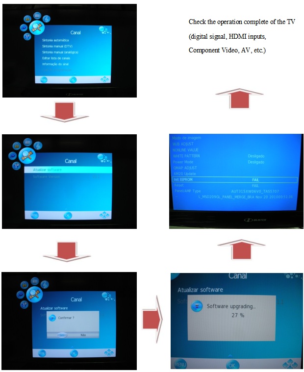
After replacing the MAIN P.C.B., be sure to achieve adjustment.
The adjustment instruction is available at "software download" on the "Support Information from NWBG/VDBG-AVC" web-site in "TSN system", together with Maintenance software.
Service Mode
The screens of the service mode are for SDR-H100P.
For other models, refer to each screen of the service mode.
1. Indication method of the service menu
Set the mode switch “Recording" mode.
2. While keep pressing the "Intelligent auto/Manual" button and "Menu" button, hold left the Zoom Lever towards to "[ W ]" position for more than 3 seconds until the top screen of the Service Menu being displayed.
HDD Self Check
Select [3] HDD self check.
HDD self check result display
Display the HDD self check result information.
Displays other than "OK" are abnormalities of HDD.
Push the menu button to end the service mode, and then POWER OFF.
Lock Search History Indication
Select [4] Lock search history indication.
• Lock search history indication
Display the camera system error code for three histories saved in EEPROM.
• The error code contents which are displayed
Lock search history indication is finished by POWER OFF.
Power ON Self Check Result Display
1. Select [5] Power ON self check result display.
• Power ON self check result display
Function to diagnose correct function of the device and interface between devices result display.
Display the following communication test result.
- CAM-PWR : Communication test between IC2006 to IC1503
- CAM-UNI : Communication test between IC2006 to IC3401
Display other than "OK" are abnormalities of each lines.
Power ON self check result display is finished by POWER OFF.
Lock Search History Clear
1. Select [10] Lock Search History Clear.
An error code for three histories in EEPROM is cleared.
Push the menu button to end the service mode, and then POWER OFF.
Cleaning Lens and LCD Panel
Do not touch the surface of the lens and LCD Panel with your hand.
When cleaning the lens, use air-Blower to blow off the dust.
When cleaning the LCD Panel, dampen the lens cleaning paper with lens cleaner, and the gently wipe the their surface.
Note: Lens cleaning paper and lens cleaner are available at local camera shops and market.
Factory Setting
The screens of the factory setting are for SDR-H100P.
For other models, refer to each screen of the factory setting.
How to turn on the factory setting
1. Indication method of the service menu.
Set the mode switch “Recording" mode.
2. While keep pressing the "Intelligent auto/Manual" button and "Menu" button, hold left the Zoom Lever towards to "[ W ]" position for more than 3 seconds until the top screen of the Service Menu being displayed.
3. Under the condition of the Item No."1" is yellow high lighted, press the "[RIGHT ] of joystick" button.
4. By pressing the "[UP ] of joystick" button, then press the "[center] of joystick" button.
5. After few seconds "END" is displayed on LCD monitor. Cutting of battery connection or AC power supply connection as a completion of the "FACTORY SETTINGS"
What is the factory settings
The factory settings clean up and/or refresh the following settings.
1. MENU, MODE, ADJUSTMENT VALUE.
2. SD card format.
3. Reset the folder number and file number of still pictures.  (Setting the folder number is 100, and file number is 0.)
4. Clear the mechanism lock information.
5. Clear the service mode information contents.
6. Clear the date.
7. Initialise the VIERA Link Physical Address.
8. Confirm the data area of HDD is cleared.

Monday 17 December 2018

LG DM2740 – How to upgrade the firmware, system reset, amplifier and MICOM schematic - DVD Micro Hi-Fi system


LG DM2740 (DM2740, CMS2730F) DVD Micro Hi-Fi System - Signal system: Standard NTSC color TV system
Stereo mode: 80 W + 80 W (4Ω at 1kHz)
 The pick-up incorporates a strong magnet, and so should never be brought close to magnetic materials.
 ✓The pick-up should always be handled correctly and carefully, taking care to avoid external pressure and impact. If it is subjected to strong pressure or impact, the result may be an operational malfunction and/or damage to the printed-circuit board.
 ✓Each and every pick-up is already individually adjusted to a high degree of precision, and for that reason the adjustment point and installation screws should absolutely never be touched.
 ✓Laser beams may damage the eyes. Never permit laser beams to enter the eyes.
Also NEVER switch ON the power to the laser output part (lens, etc.) of the pick-up if it is damaged.
✓ NEVER look directly at the laser beam, and don’t allow contact with fingers or other exposed skin.
 ✓Never attempt to disassemble the pick-up.
Spring has excess pressure. If the lens is extremely dirty, apply isopropyl alcohol to the cotton swab.
(Do not use any other liquid cleaners, because they will damage the lens.) 
✓Take care not to use too much of this alcohol on the swab, and do not allow the alcohol to get inside the pick-up.
FIRMWARE UPGRADE
MPEG
1) Copy firmware to USB (Do not change file name).
Ex) LG_DM2740LD1_1403190.rom
2) Change function to DVD/CD by pressing input key, and wait until home menu is shown.
3) Inset USB device which includes firmware.
4) Firmware is detected automatically and then, shows blue screen in TV. If home menu is maintained after inserting USB, press music Icon.
5) Take off the USB and press PLAY key.
6) and then, upgrading is started.  Do not turn off the set until upgrade is finished.
7) After finishing firmware upgrading, set will restart automatically.
8) Power off and on again by pressing POWER key.
AUDIO MICOM
1) Copy firmware to USB (Do not change file name).
Ex) DM2740_1403250.HEX
2) Change function to DVD/CD by pressing input key, and wait until home menu is shown.
3) Inset USB device which includes firmware.
4) Firmware is detected automatically and then, shows blue screen in TV.
If home menu is maintained after inserting USB, press music Icon.
5) Upgrading is started.
 Do not turn off the set until upgrade is finished.
 Do not pull out the USB device using firmware upgrading.
6) After finishing firmware upgrading, set will be turned off.
TOUCH
1) Copy firmware to USB (Do not change file name).
Ex) DM2740T_1402040.dld / TC390_LG_CMDM2740_140204_0.hex
2) Change function to DVD/CD by pressing input key, and wait until home menu is shown.
3) Inset USB device which includes firmware.
4) Firmware is detected automatically and then, shows blue screen in TV.  If Home menu is maintained after inserting USB, press music Icon.
5) Upgrading is started.
  ✓Do not turn off the set until upgrade is finished.
  ✓Do not pull out the USB device using firmware upgrading.
6) After finishing firmware upgrading, set will be turned off.
EEPROM OPTION SETTING
1) Change function to DVD/CD by pressing input key, and wait until home menu is shown.
Do not insert disc or USB at the set.
2) Press "PAUSE 1 4 7 2" in order.
3) and then, option setting menu is displayed.
You can see 10 bytes option value.
Ex ) F9 00 C1 D4 00 11 90 10 E0 08
4) Move a cursor by pressing Arrow </> key.
5) Press Num key what you want to change.
6) Press "PAUSE" key to exit option setting menu.
After change option value, you need to make system reset.
Power AMP schematic
MICOM schematic
SMPS schematic
SYSTEM RESET
1) Change function to DVD/CD by pressing input key, and wait until home menu is shown.
 Do not insert disc or USB at the set.
2) Go to SETUP menu by pressing SETUP button in HOME menu.
3) Move highlight at "DISPLAY ==> TV Aspect ==>16:9".
4) Press "1 3 9 7 1 3 9 Enter" in order.
5) And then, system reset menu is displayed.
6) Power off and on by pressing POWER key.

Wednesday 21 November 2018

Toshiba 43L2500, Toshiba 40L1500 - SMPS, LVDS, Audio output, Back-light Inverter circuit diagram (Schematic)


Toshiba 43L2500, Toshiba 40L1500, Toshiba 32L1500, Toshiba DL3253 – SMPS, LVDS, Audio output, Back-light Inverter circuit diagram (Schematic)
SMPS - EM8635 (SMPS control), 6N65 (SMPS power switching)
Backlight inverter – QZ9902C (Back-light inverter control)
Audio output – STA33W
LVDS connector
Toshiba 32L1500/40L1500/DL3253 – LVDS 

Friday 2 November 2018

HBTV-32D02FD, HBTV-40D02FD – H Buster – service mode, software update, connector voltage details


Be sure no power is applied to the chassis or circuit, and observe all other safety precautions.
Service Mode
With the TV remote control, enter the following keys in sequence:
[MENU 8 8 9 3]
The TV screen will display the information as shown below.
In the last line of the service menu, the card version.
Such as: "L_MSD209GL_PANEL_MERGE BRA MAY 13 201016.47.31"
Exiting service mode
Simply press the EXIT button on the user's remote control or turn the power off.
ATTENTION:
When performing a software update, memory swapping
If the EEPROM or the device shows unstable, perform the below:
Press the UP / DOWN buttons and select Init EEPROM, then press the ">" button.
seconds for execution.
NOTE: After "reset", turn the unit off and on again.
Firmware Update
This procedure should only be performed when the equipment is abnormal in its operation, or when there is an official communiqué to carry out such a procedure.  Do not upgrade if the equipment is working properly.  Carefully read the entire procedure and perform the task as described below.  If in doubt, always seek the help of H-Buster technical support.
Firmware (software update)
Initial Procedures.
Needed tools:
- An empty and formatted pen drive (FAT32) - minimum 512MB;
- Remote control of equipment;
- Latest version downloaded from the services website.
To obtain the latest version, log on to the H-Buster service website and download as the LCD panel model (if present). If you have any questions, contact technical support.
How to identify the Panel Type
Service Mode Menu
Rear side of LCD Panel
Identification of the LCD panel by the label attached to the reverse (inner part)
Copying the firmware to USB Memory Key
The file that is on the services site is "zipped (compressed)." To unzip it, it is necessary to have a decompress program installed on your computer (eg Winzip, WinRAR, etc.) Save to the desktop and unzip it to the PC. If the decompress or program creates open the folder and copy to the pen-drive the file that is inside the folder (NOT COPY TO ALL PASTE).
The name of the file to be copied to the pen drive SHOULD NOT BE CHANGED, CASE CONTRARY TV WILL NOT RECOGNIZE THE FILE
Updating the firmware
Follow the procedures below carefully:
1) With the TV working, connect the pen drive with the recorded program to the USB port;
2) Press the MENU button on the remote control and go to the CHANNEL option with the navigation keys and press OK;
3) In the CHANNEL menu, scroll to the next page where "Update Software" will appear and press OK;
4) The confirmation question will appear on the screen, confirm and press OK;
5) Wait until the end of the update, where the equipment will turn off and restart itself;
6) Enter the service menu and reset the memory with the INIT EEPROM command.
Firmware Update Diagram
Check the operation complete of the TV (digital signal, HDMI inputs, Component Video, AV, etc.)
Power Supply Board Failure Check.
State:No picture
First,check cables which connect with PSU,then check as follows
Check input voltage
voltage: +5VSB----POWER ON(2.6V) --+12V
State: No sound
First,check cables which connect with PSU,then check as follows
1) Check input voltage as NO picture
2) Check speaker output
check speaker anode(+) and cathode(-), confirm speaker short or not.  If any defect found replace the speaker.
Audio output stage schematic
Main board of HBTV-32D02FD / HBTV-40D02FD boards locations.
HBTV-32D02FD
Mainboard-HBTV-32D02FD / HBTV-40D02FD-Connector definition
Power Supply Board-Connector definition: HBTV-32D02FD
HBTV-40D02FD-LED LIPS AC input pin configuration
LCD Panel-Display the signal-Connector definition-HBTV-32D02FD
HBTV-40D02FD Input signal and power
Note1: No Connection: These PINS are used only for SAMSUNG. (DO NOT CONNECT)
Note2: LVDS OPTION : If this PIN is:
HIGH (3.3 V) Normal LVDS format
LOW (GND) JEIDA LVDS format
SEQUENCE : On = VDD(T1)  LVDS Option  Interface Signal(T2)
OFF = Interface Signal(T3)  LVDS Option  VDD.

Monday 8 October 2018

How to enter service mode – Samsung UE Series – U8DC chassis - 32, 40, 48 and 50 inch LED TVs, How to update the firmware, troubleshooting


Samsung LED TV – UE32H5500, UE40H5500, UE48H5500, UE50H5500 – troubleshooting, connector voltage chart and more
Software Upgrade
Samsung may offer upgrades for the TV’s firmware in the future. These upgrades can be performed via the TV when it is connected to the Internet, or by downloading the new firmware from samsung.com to a USB memory device.
• Alternative Software (Backup) shows The previous version that will be replaced.
• Software is represented as ‘Year/Month/Day_Version’. The more recent the date, the newer the software version Installing the latest version is recommended.
By USB
Insert a USB drive containing the firmware upgrade downloaded from samsung.com into the TV. Please be careful to not disconnect the power or remove the USB drive while upgrades are being applied. The TV will turn off and turn on automatically after completing the firmware upgrade. Please check the firmware version after the upgrades are complete (the new version will have a higher number than the older version). When software is upgraded, video and audio settings you have made will return to their default (factory) settings. We recommend you write down your settings so that you can easily reset them after the upgrade.
By Online
Upgrades the software using the Internet.
• First, configure your network. For detailed procedures on using the Network Setting, refer to the ‘Setting the Network’ instructions.
• If The internet connection doesn’t operate properly, connection can be broken, please retry downloading. If the problem still happens, download by USB and upgrade.
Alternative Software (Backup)
If there is an issue with the new firmware and it is affecting operation, you can change the software to the previous version.
• If Software was changed, existing Software is displayed.
• you can change current Software to Alternative Software by ‘Alternative Software’.
Troubleshooting: Previous Check
1. Check the various cable connections frst.
- Check to see if there is a burnt or damaged cable.
- Check to see if there is a disconnected or loose cable connection.
- Check to see if the cables are connected according to the connection diagram.
2. Check the power input to the Main Board.
3. How to distinguish if the problem is caused by Main Board or T CON
How to know it is from Main Board or T-Con when some problems happen
1. No Picture : Backlight is on, but there is no picture and LED indicator in front of TV is blinking.
- Check the LVDS Cable connection. If still problems, change the T-Con Board and then Main Board step by step.
2. Picture distortion : Enter the service mode
Choose ‘SVC’ Check the ‘internal pattern.’
To  Enter ‘Service Mode.
3. Choose ‘SVC.’
4. Choose ‘Test pattern.’
5. Select the each pattern and then check all pattern is ok or not.
* If pattern status is OK, fault might be at its main board. Front of the NOVATEX IC has the problem.
* If pattern is not good, Panel and T-Con board should be suspected.
NO Power problem
If you replace the main board with new one, change the factory option as well.
The options you must change are "Type".
Main board - connector voltage details
White Balance:  Calibration
1. Into the Factory Mode.
2. Select ADC/WB menu.
3. Select ADC menu.
Service Adjustment
You must perform Calibration in the Lattice Pattern before adjusting the White Balance.
Method of Color Calibration (AV)
1. Apply the NTSC Lattice (N0. 3) pattern signal to the AV IN 1 port.
2. Press the Source key to switch to “AV1” mode.
3. Enter Service mode.
4. Select the “ADC” menu.
5. Select the “AV Calibration” menu.
6. In “AV Calibration Off” status, press the “► ” key to perform Calibration.
7. When Calibration is complete, it returns to the high-level menu.
8. You can see the change of the “AV Calibration” status from Failure to Success.
Method of Color Calibration (Component)
1. Apply the 720p Lattice (N0. 6) pattern signal to the Component IN 1 port.
2. Press the Source key to switch to “Component1” mode.
3. Enter Service mode.
4. Select the “ADC” menu.
5. Select the “Comp Calibration” menu.
6. In “Comp Calibration Off” status, press the “ ►” key to perform Calibration.
7. When Calibration is complete, it returns to the high-level menu.
8. You can see the change of the “Comp Calibration” status from Failure to Success.
Method of Color Calibration (HDMI)
1. Apply the 720p Lattice (N0. 6) pattern signal to the HDMI1/DVI IN port.
2. Press the Source key to switch to “HDMI1” mode.
3. Enter Service mode.
4. Select the “ADC” menu.
5. Select the “HDMI Calibration” menu.
6. In “HDMI Calibration Off” status, press the “►” key to perform Calibration.
7. When Calibration is complete, it returns to the high-level menu.
8. You can see the change of the “HDMI Calibration” status from Failure to Success.

Thursday 4 October 2018

CM8350 LG Hi-Fi system – How to update the software, Hidden key modes, SMPS and Main AMP schematic

LG CM8350 (CM8350, CMS8350F) HI Fi system
Program download: Audio program
Download program file name must be MICOM_CM8450_YYMMDDX.HEX
If security program(Water Wall) is activated on PC, you must save the file to the USB storage device and disable the security software, then download the file to your set.
Downloading file proceeds in the same way at USB1 function and USB2 function.
Caution: When downloading the file, you should neither unplug the USB device, change to the other function, nor power off the device. USB device must be unplugged when the downloading process is completed.
CD program
Download program file name must be HG580_CM8450_YYMMDDX.bin
If security program(Water Wall) is activated on PC, you must save the file to the USB storage device and disable the security software, then download the file to your set.
Downloading file proceeds in the same way at USB1 function and USB2 function.
Caution: When downloading the file, you should neither unplug the USB device, change to the other function, nor power off the device. USB device must be unplugged when the downloading process is completed.
EQ program
Download program file name must be EQ_PRG.BIN
If security program(Water Wall) is activated on PC, you must save the file to the USB storage device and disable the security software, then download the file to your set.
Downloading file proceeds in the same way at USB1 function and USB2 function.
Caution: When downloading the file, you should neither unplug the USB device, change to the other function, nor power off the device. USB device must be unplugged when the downloading process is completed.
SMPS schematic
Main AMP schematic
Hidden key mode
Service information for EEPROM

Sunday 23 September 2018

Noblex 20TC662 – How to enter the service mode, full schematic, service adjustments


Noblex Model No. 20TC662 – How to enter the service mode, full schematic, service adjustments PAL (M/M, N/N), NTSC (M/M) (Argentina) Colour Television
Service Adjustments
This set has an On-screen Service Menu system included in the CPU thar allows remote operation for most of the service adjustments.
Enter the Service Menu
While pressing the MENU button on the television, press the Number Key 2 on the remote control unit. The Service Menu now appear.
Service Adjustments:
Press the CHANNEL UP or CHANNEL DOWN button on the remote control handset to select the desired service menu item you want to adjust.
Use the VOLUME + or - to adjust the data. The + or - button will increase or decrease the data sequentially.
Exit from the Service Menu
Press the MENU button to turn off the Service Menu display.
The data which is set in the service mode is stored into the memory IC automatically.
The initial values which have been stored in the CPU ROM, and items for the service adjustments.
Do not attempt to adjust service adjustments not listed on below otherwise it may cause loss of performance and for correct operation.
Click on the pictures to magnify
[RFAGC] AGC
Do not attempt this adjustment with weak signal.
(1) Tune the receiver to most clearest (or strongest) VHF station in your area. Set the brightness and contrast controls to maximum. Set the colour control to minimum.
(2) Select Item No. 01 [RFAGC] in the service mode.
(3) Change value until the snow noise just disappears.
(4) Exit from the service mode.
[H-PHA] HORIZONTAL CENTRE
(1) Receive a monochrome circular pattern.
(2) Set the brightness and contrast to normal.
(3) Select Item No. 02 [H-PHA] in the service mode.
(4) Change value to be optimum horizontal centre position.
(5) Exit from the service mode.
[V-POS] VERTICAL CENTRE
(1) Receive a monochrome circular pattern.
(2) Set the brightness and contrast to maximum.
(3) Select Item No. 03 [V-POS] in the service mode.
(4) Change value to be optimum vertical centre position.
(5) Exit from the service mode.
[V-SIZ] VERTICAL SIZE
(1) Receive a monochrome circular pattern.
(2) Set the brightness and contrast to maximum.
(3) Select Item No. 04 [V-SIZ] in the service mode.
(4) Change value to be optimum vertical size.
(5) Exit from the service mode.
[OSDHP] OSD POSITION
(1) Receive a monochrome circular pattern.
(2) Set the brightness and contrast to normal.
(3) Select Item No. 12 [OSDHP] in the service mode.
(4) Change value to be proper OSD position.
(5) Exit from the service mode.
[AFCRF] AFC GAIN
(1) Switch on the TV.
(2) Select Item No. 65 [AFCRF] in service mode.
(3) Change data value to “01”.
(4) Exit from the service mode.
[CCD] CAPTION H-POSITION ADJ
(1) Tune receiver to a caption channel.
(2) Check that CAPTION position is in the horizontal center of the screen. If CAPTION center is too right or left, perform steps 3-6.
(3) Select Item No. 85 [CCD] in the service mode.
(4) Adjust data with + or - key for proper horizontal center.
(5) Exit from the service mode
GREY SCALE
(1) Receive a monochrome circular pattern.
(2) Set the brightness and colour to normal, contrast to maximum.
(3) Enter to the service mode.
(4) Set each value of Item-16 RBIAS, 17 GBIAS, 18 BBIAS mode to 00. Set each value of Item-19 RDRIV, 21 BDRIV mode to 63, 20 GDRIV to 07.
(5) Select Item-22 mode to be one horizontal scanning line and turn the screen volume on the FBT to obtain just visible one colored line.
(6) Press the 1 (Red Bias +), 4 (Red Bias -), 2 (Green Bias +), 5 (Green Bias -), 3 (Blue Bias +) or 6 (Blue Bias -) button to adjust the brightness of each colour until a dim white line produced. Please see the control button allocations in this mode.
(7) Select Item-23 DRV mode to enter the white balance adjusting mode.
(8) Press the 7 (Red Drive +), RECALL (Red Drive -), 8 (Blue Drive +) or 0 (Blue Drive -) button alternately to produce normal black and white picture.
(9) Exit from the service mode.
(10) Check for proper grey scale tracking at all brightness levels.
NOTE: If the grey scale adjustment is made after picture tube replacement, check the high voltage.
FINE TUNING
This adjustment is used to do a fine tuning of the channels with poor reception after they have been stored by the automatic tuning.
This function is available for one channel only and the fine-tuned channel is memorized into IC802 (EEPROM).
Enter Service Menu
While pressing the MENU button on the television, press the “4” or MENU button on the remote control unit. The Service Menu now appear.
Press and hold the VOLUME + or VOLUME – button on the remote control handset or TV set to make fine tuning adjustment. Press and hold the VOLUME + button for higher frequency tuning, and press and hold the VOLUME - for lower frequency tuning.
Fine tuning data value will be automatically stored in memory.
To return to normal TV mode, press the MENU button on the TV set or remote control handset. (Or will automatically return to normal TV mode after 5 seconds.)
FOCUS ADJUSTMENT
(1) Receive the monochrome circular pattern.
(2) Set the brightness to normal and contrast to maximum.
(3) Adjust the focus control on the F.B.T. for the best focus on the screen centre.
+B POWER SUPPLY ADJUSTMENT
1. Connect a DC voltmetre to TP-”+B +130V” and the ground. Set the +B adjustment control (VR651) to middle range.
2. Set the brightness to normal and contrast to maximum.
3. Tune the receiver to anactive channel and synchronized picture.
4. Adjust +B voltage to 130± 1.0 volt DC by using VR651.
HIGH VOLTAGE CHECK
Note: +B (+130V) Voltage Check and Grayscale Adjustment must be completed before attempting High Voltage Check.
(1) Connect high voltage voltmeter negative lead to ground, and connect + lead to anode of picture tube.
(2) Tune receiver to an active channel and confirm TV is operating properly.
(3) The high voltage must be 14”=21KV ± 1KV, 20”/21”=25KV ± 1KV, 29”=26.5KV ± 1KV and less than 14”=25KV, 20”/21”=27.5KV, 29”=29.5KV at 0 beam current (Brightness and contrast minimum setting).
Note: If the picture tube is replaced, check the high voltage. The horiz. width adjustment affects the high voltage. Therefore, re-check the high voltage.
Full Schematic [Circuit diagram]
Protection Circuit
This TV set has a built-in power supply protection circuit.
It is provided to protect the TV set in case of a power supply circuit malfunctions. When something abnormality occurs during TV reception, the TV set goes to the standby mode.
When an abnormality occurs during TV reception, it causes pin 27 of the CPU to go continually Low voltage for about one second. The CPU detects that this has occurred and outputs the signal from pin 31 to switch off the power supply lines.
Releasing the protective circuit and restoring power supply
To release the protective circuit and restore power supply, turn the power to the TV set OFF and then ON again via either the main power switch or the ON-OFF button on the remote control. This will work only if the power supply trouble was temporary. If there is permanent trouble such as a damaged circuit, power cannot be restored and the circuit will have to be repaired.
Purity and Convergence Adjustment
The Convergence and Purity adjustments have been made at the factory. Readjustment should be made only after picture tube or deflection yoke replacement, following the steps below
PURITY ADJUSTMENT
1. Demagnetize the picture tube and receiver using an external degaussing coil. When replacing picture tube or deflection yoke, mount deflection yoke and purity-convergence magnets assembly properly,
2. Turn Red and Blue guns off and provide only Green raster.  Rotate Screen control to fully counterclockwise. Rotate Red and Blue Bias controls fully counterclockwise. Slowly rotate Green Bias control clockwise to produce Green raster.
3. Loosen the screw holding the Deflection Yoke and remove the 3 Rubber Wedges, and slide the Deflection Yoke fully forward.
4. Rotate and spread the Tabs of the two Purity Magnets to centre the vertical green belt in the picture screen. The Purity Magnets are also adjusted to obtain vertical centering of the raster.
5. Slowly slide the Deflection Yoke backward until a uniform green screen is obtained.
6. Check the purity of the red and blue screens for uniformity, turn off other colors to check this (use bias controls).  Readjust the yoke position if necessary until all screens are pure.
7. Adjust each Bias control and screen control to obtain white raster. Refer to Gray Scale Adjustment. If part of the picture screen is coloured, adjust the Deflection Yoke position forward or backward slightly.
8. Tighten the mounting screw of the Deflection Yoke. Adjust Convergence next.
CENTRE CONVERGENCE ADJUSTMENT
1. Use a dot crosshatch pattern signal.
2. Turn Red and Blue guns on and turn off Green gun. Adjust the angle between the Tabs of the Four Pole Magnet 1 and 2, and superimpose the Red and Blue vertical lines in the centre area of the picture screen.
3. Keeping the mutual angle of the Tabs of the Four Pole Magnet turn them together to superimpose the Blue and Red horizontal lines in the centre area of the picture screen.
4. Turn Green gun on and adjust Six Pole Magnet 3 and 4 that the Green line superimposed on the Red/Blue lines.  This is the same procedure used in steps 2 and 3.
OUTER AREA CONVERGENCE ADJUSTMENT
Slightly loosen the screw holding the Deflection Yoke. Adjust the Deflection Yoke to converge the detail in the outer area (left side and right side) of the picture screen by orbital movement of the front of the Yoke, then secure the Deflection Yoke in appropriate position by putting the wedges as illustrated. Tighten screw holding the Deflection Yoke.
Universal Remote Control Codes, Setup procedure, Circuit diagrams and more ....