How to enter the service mode, service adjustments, and factory settings
Press the RC buttons in
this sequence: “Menu 1 1 4 7” to enter the factory menu.
Service menu (Factory
Menu) descriptions.
SHIPPING INIT
BURNNG MODE
ADC ADJUST
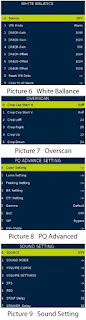
PICTURE SETTING
SOUND SETTING
GENERAL SETTING
DEBUG
PANEL SETTING
EMC SETTING
SW INFORMATION
BOARD INIT
SW UPGRADE
OTA SETTING
FACTORY SETTING
SHIPPING INIT: TV Initialization and
all parameter to be default. Designed for Shipment.
BURNING MODE: For test panel. If
it’s in
operation, use key board “power” to quit.
ADC ADJUST: Change ADC
parameters
PICTURE SETTING: Change Picture
Setting
SOUND SETTING: Change Sound Setting
GENERAL SETTING: Some other
settings usually used, and also for Debug
DEBUG: Debug mode.
PANEL SETTING: Change panel
parameters
EMC SETTING: Some settings may
affect EMC
SW INFORMATION: Display some
system information.
BOARD INIT: Initialize TV, restore
to factory configuration.
|
SW UPGRADE: Software update item. |
Board Type: Display
board type
Build Time: Display Firmware
build time
HDCP Check: HDCP key status
MAC Address: MAC Address

Software upgrading
The rules of USB upgrade file name
The
upgrade file name must be "allupgrade-6486-SOS.bin"
Preparation
Prepare (6486 board) for upgrading.

Upgrade Introduce
Copy
the upgrade file into the USB Flash Disk.
Insert the USB Flash Disk Into the USB PORT of 6486 board.
Turn On your 6486 board.
If the upgrade file is correct, the software will begin upgrade automatically.
Upgrade interface
Upgrade interface
Upgrade Introduce
Copy
the upgrade file into the USB Flash Disk.
Insert the USB Flash Disk Into the USB PORT of 6486 board.
Turn On your 6486 board.
If the upgrade file is correct, the software will begin upgrade automatically
Darning upgrade process, screen will display upgrade progress
information, and please do not turn off your TV, it will reboot automatically
while the upgrade is complete.
100% mean the upgrade is complete, then pull out USB storage and restart TV
Error means upgrade
fail. If upgrade fails, please turn off your TV and try to upgrade again.

Led flash mode
Durning
upgrade process, we can know about the upgrade status from the LED flash mode.
During upgrade
RED
1000ms GREEN 1000ms flashing, until upgrade succeed or fail.
Upgrade succeed
RED
250ms GREEN 250ms flashing, Long time to blink until power off.
Upgrade fail
RED
1750ms GREEN 250ms flashing, Long time to blink until power off.
Mboot upgrade.
For Secure Chip.
1.
Connect the Uart debug tool, Disconnect the tool which you used to get log
information.
2. Open the MSTV-Tool.exe.
3. Press the button “Show Device ID” to show the Device ID.
4. Search the device ID
you get in the “6486DevciceID.xlsx” file, you will find a key string above the
device ID string. If you can not find the device ID in the file, please send
you device ID to us (caihuaqin@cvte.com),we will send the key to you.
5. Select
View->OpenDebugPort and enter the OpenDebugPort menu, input the key string you
get in step4 at the OpenDebugPort menu and press Run button of the
OpenDebugPort menu. Check and make sure run successfully.

6. Select “Help->
Product Key” and enter Product Key menu, input “prognand” command in the Product
Key menu and press “OK” Button.7. Select View -> NAND Program (8051) and
enter the following Menu. In the Menu, select the files need as bellow, then
press “program” button.
Prepare stage – 1.Maldives-PM51-Prepare.txt
DRAM script-2Munich-DDR3-32-MIU0-1-1600-17x17.txt
Tool bin File – 3
PM51-Maldives.bin
Rom Boot Bin File – 4.RomBoot.bin
Trigger stage – 5.Maldives-PM51-Trigger.txt

8. After program
successfully, disconnect the AC plug, put the upgrade file the USB stick and plug
the usb stick in the main board, connect the tool (such as SecureCRT) which you
used to get the log with the tv by the uart debug tool.
9. Set the PC cursor in
the window which can show the log information and press the Enter button of
your PC keyboard, do not release the Enter button and connect the AC power,
then you will enter the Mboot of the TV(as the following picture). In the
Mboot, you can input some command to set the tv system.
10. Input “cu” command in the Mboot and press Enter, then the TV will start to upgrade.
For None Secure Chip
1.
Connect the Uart debug tool, Disconnect the tool which you used to get log
information.
2. Open the MSTV-Tool.exe.
3. Select “Help-> Product Key” and enter Product Key menu, input “prognand”
command in the Product Key menu and press “OK” Button.
4. Select View ->
NAND Program (ARM/MIPS) and enter the following Menu. In the Menu, select the
files need as bellow, then press “program” button.
Prepare stage – 1ARM-Munich-Prepare.txt
DRAM script – 2Munich-DDR3-32-MIU0-1-1600-17x17.txt
Tool bin File – 3-tool.bin
Rom Boot Bin File – 4RomBoot.bin
Trigger stage – 5ARM-Munich-Trigger.txt

5. After program
successfully, disconnect the AC plug, put the upgrade file the USB stick and plug
the usb stick in the main board, connect the tool (such as SecureCRT) which you
used to get the log with the tv by the uart debug tool.
6. Set the PC cursor in
the window which can show the log information and press the Enter button of
your PC keyboard, do not release the Enter button and connect the AC power,
then you will enter the Mboot of the TV (as the following picture). In the
Mboot, you can input some command to set the tv system.
7. Input “cu” command in
the Mboot and press Enter, then the TV will start to upgrade.