EAY38730101-32F1-LG-SMPS SCHEMATIC
Used ICs: FA5501AN, MC80F0308, NCP1271B, STP6NK90ZEP, NCP1207

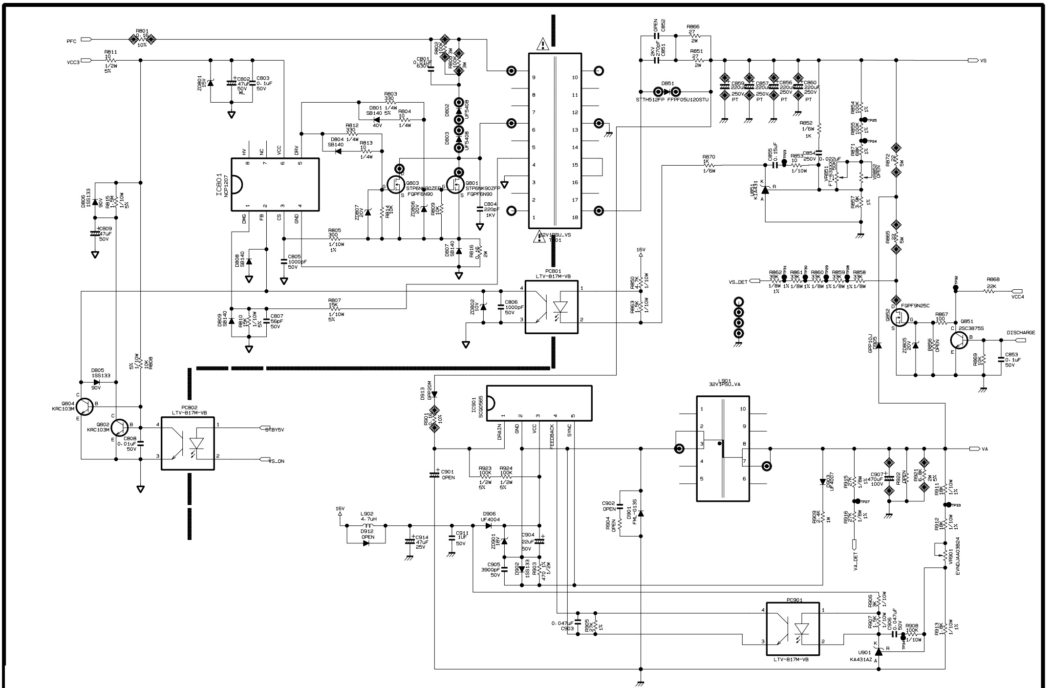


BN44-00422B Samsung SMPS schematic


EAY38730101-32F1-LG-SMPS SCHEMATIC
Used ICs: FA5501AN, MC80F0308, NCP1271B, STP6NK90ZEP, NCP1207
BN44-00422B Samsung SMPS schematic

If 32HFL5014/12 works very slow, it hangs, or you have a full memory and you want to erase everything, or you want to sell it or give it away and you want nobody to be able to access your history and passwords you can do a factory reset or format so that it returns to be like the first day.
IMPORTANT: Formatting or
resetting your Philips 32HFL5014/12 to its factory state will eliminate all the
personalized settings of the television such as the tuned channels and their
order, input names, applications that have been installed, passwords of the
accounts linked to this 32HFL5014/12, Wi-Fi passwords, Google Play user and web
browsing history. The Philips 32HFL5014/12 TV will need to be fully configured
as when it was turned on for the first time after purchase.
* Go to the start menu of Philips
32HFL5014/12 TV 81.3 cm (32") Full HD Smart TV Wi-Fi Black TV, go to the settings; it is the gear wheel icon in the
upper right part of the screen of your Philips 32HFL5014/12 TV 81.3 cm
(32") Full HD Smart TV Wi-Fi Black:
* Navigate
through the menu of the 32HFL5014/12 TV and find the section called
"Storage and reset", press to access the storage settings and factory
restore.
* Once
inside the Philips 32HFL5014/12 Storage and reset settings, we look for the
"Factory data reset" section with our remote or cursor and click on
it.
* A confirmation message will appear on the screen
of the Philips 32HFL5014/12 indicating that all the information on the
television 32HFL5014/12 will be earased, including the settings, the downloaded
applications and the link with your Google account (the Google account is not earased only unlinked from the TV), click on "Factory data reset"
again, if you have decided not to continue click "Cancel" and no data
will be erased.
* A second confirmation message will appear to
confirm that you want to restore
the Philips 32HFL5014/12; from this step you cannot go back,
all apps and settings will be removed from the TV.
Press "Erase
everything" to finish and wait a few seconds.
Will take some time to finish the reset.
If you
want to restore
default settings on PHILIPS 32PFS5803/12, perform
the hard reset operation.
As a result, you will delete all personal info, customized settings and installed
apps on your PHILIPS 32PFS5803/12.
Check out how to hard reset PHILIPS
32PFS5803/12 and wipe
all personal data from the TV. It's the easiest way to
bring back the default
software configuration.
* Press the Power button on
the remote controller.
* After the TV turns on, press the Settings button on the remote
control.
* When the menu opens, use
the Arrow buttons on
the remote to move around the menu.
* Select All settings and
press the OK button on
the remote.
* Scroll down and select General settings and press the Arrow right button to Enter.
If asked for a PIN Enter Yours.
* Select "Yes" and press the OK button on the remote to confirm.
Applicable to:
|
22PFT4232/12 |
|
32PFS4132/12 |
|
32PFT4132/05 |
|
32PFT4132/12 |
|
32PFT4132/60 |
|
32PHS4132/12 |
|
32PHT4132/05 |
|
32PHT4132/12 |
|
32PHT4132/60 |
|
43PFS4132/12 |
|
43PFT4132/05 |
|
43PFT4132/12 |
|
43PFT4132/60 |
|
49PFS4132/12 |
|
49PFT4132/12 |
|
32PHS4112/12 |
|
32PHT4112/05 |
|
32PHT4112/12 |
|
39PHS4112/12 |
|
39PHT4112/05 |
|
39PHT4112/12 |
|
43PFS4112/12 |
|
43PFT4112/05 |
|
43PFT4112/12 |
|
4PFS4032/12 |
|
24PFT4032/12 |
|
24PFT4032/60 |
|
24PHS4032/12 |
|
24PHT4032/05 |
|
24PHT4032/12 |
|
24PHT4032/60 |
|
32PHS4032/12 |
|
32PHT4032/05 |
|
32PHT4032/12 |
|
32PHT4032/60 |
|
22PFS4022/12 |
|
22PFT4022/05 |
|
22PFT4022/12 |
|
22PFT4022/60 |
|
24PFS4022/12 |
|
24PFT4022/12 |
|
24PFT4022/60 |
|
24PHS4022/12 |
|
24PHT4022/05 |
|
24PHT4022/12 |
Service Modes
The
Service Mode feature is split into following parts:
Service Alignment Mode (SAM).
Factory
Mode.
Customer Service Mode (CSM).
SAM and the Factory mode offer features, which can be used by the Service
engineer to repair/align a TV set. Some features are:
Make alignments (e.g. White Tone), reset the error buffer(SAM and Factory
Mode).
Display information (“SAM” indication in upper right corner of screen, error
buffer, software version, operating hours,options and option codes, sub menus).
The CSM is a Service Mode that can be enabled by the consumer.
The CSM displays diagnosis information, which the customer can forward to the dealer or call centre. In CSM mode, “CSM”, is displayed in the top right corner of the screen.
The information
provided in CSM and the purpose of CSM is to:
Increase the home repair hit rate.
Decrease the number of nuisance calls.
Solved customers’ problem without home visit.
Note: For the new model range, a
new remote control (RC) is used with some renamed buttons. This has an impact
on the activation of the Service modes.
For instance the old “MENU” button is now called “HOME” (or is indicated by a
“house” icon).
Service Alignment Mode (SAM)
Specifications
Operation
hours counter (maximum five digits displayed).
Software version, error codes, and option settings display.
Error buffer clearing.
Option settings.
Software alignments (White Tone).
NVM Editor.
Set screen mode to full screen (all content is visible).
How to Activate SAM
To
activate SAM, use one of the following methods:
Press the following key sequence on the remote control transmitter: “062596”, directly followed by the “INFO/OK”
button. Do not allow the display to time out between entries while
keying the sequence.
Or via ComPair.
After entering SAM, the following items are displayed,
with “SAM” in the upper right corner of the screen to indicate that the
television is in Service Alignment Mode.
How to Navigate
In
the SAM menu, select menu items with the UP/DOWN keys on the remote control
transmitter. The selected item will be indicated. When not all menu items fit
on the screen, use the UP/DOWN keys to
display the next/previous menu items.
With the “LEFT/RIGHT” keys, it is possible to:
(De) activate the selected menu item.
(De) activate the selected sub menu.
Change the value of the selected menu item.
How to Store SAM Settings
To
store the settings changed in SAM mode (except the RGB Align settings), leave
the top level SAM menu by using the POWER button on the remote control transmitter
or the television set. The mentioned exceptions must be stored separately via
the STORE button.
How to Exit SAM
Use
one of the following methods:
Switch the set to STANDBY by pressing the mains button on the remote control
transmitter or the television set.
Via a standard RC-transmitter, key in “00” sequence.
Note: When the TV is switched
“off” by a power interrupt while in SAM, the TV will show up in “normal
operation mode” as soon as the power is supplied
again. The error buffer will not be cleared.
SAM mode overview


Factory mode:
Displaying
and or changing Panel ID information.
Displaying and or changing Tuner ID information.
Error buffer clearing.
Various software alignment settings.
Testpattern displaying.
Public Broadcasting Service password Reset. etc.
How to Activate the Factory mode
To
activate the Factory mode, use the following method:
Press the following key sequence on the remote control transmitter: from the “menu/home” press “1999”, directly followed by the “Back/Return”
button.
Do not allow the display to time out between entries while keying the sequence.
After entering the Factory mode, we can see many items displayed, use the UP/DOWN keys to display the
next/previous menu items
How to Exit the Factory mode
Use
one of the following methods:
Select EXIT-FACTORY from the menu and press the “OK” button.
Note: When the TV is switched
“off” by a power interrupt, or normal switch to “stand-by” while in the factory
mode, the TV will show up in “normal operation
mode” as soon as the power is supplied again. The error buffer will not be
cleared.
Customer Service Mode (CSM)
Purpose
The
Customer Service Mode shows error codes and information on the TVs operation
settings.The call centre can instruct the customer (by telephone) to enter CSM
in order to identify the status of the set.This helps the call centre to
diagnose problems and failures in the TV set before making a service call. The
CSM is a read-only mode; therefore, modifications are not possible in this
mode.
Specifications
Ignore “Service unfriendly modes”.
Line number for every line (to make CSM language independent).
Set the screen mode to full screen (all contents on screen is visible).
After leaving the Customer Service Mode, the original settings are restored.
Possibility to use “CH+” or “CH-” for channel surfing, or enter the specific
channel number on the RC.
How to Activate CSM
To
activate CSM, press the following key sequence on a standard remote control
transmitter: “123654” (do not
allow the display to time out between entries while keying the sequence). After
entering the Customer Service Mode, the following items are displayed. use the Right/Left keys to display the next/previous
menu items
Note: Activation of the CSM is
only possible if there is no (user) menu on the screen.
How to Navigate
By
means of the “CURSOR-DOWN/UP” knob (or the scroll wheel) on the RC-transmitter,
can be navigated through the menus.
How to Exit CSM
To
exit CSM, use one of the following methods.
Press the MENU/HOME button on the remote control transmitter.
Press the POWER button on the remote control transmitter.
Press the POWER button on the television set.
Software Upgrading, Error code and Panel Code
Software Upgrading.
The following update is for .pkg file.
1.
Rename the file to “upgrade_loader.pkg”
2. Prepare a USB memory.
3. Copy the software to USB flash disk(root directory).
4. Switch off the TV and Insert the USB memory stick that contains the software
update files in one of the TV’s USB 2.0 ports.
Note: It contains USB3.0 port, if connect on it, the software may can’t be
detected.
5. Switch on the TV. The TV will detect the USB memory s tick automatically.
6. When the TV software is
updated, the TV will turn on again automatically. Remove your USB flash drive.
7. We can enter in CSM or Factory mode to check the current software version.
The following update is for .upg file.
Step 1:
Ready for F/W Upgrade
1.
Prepare a USB memory.
2. Copy the software to USB flash disk(root directory).
Note the version of this F/W before you change the software file name.
Step 2: F/W Upgrade
1.
Plug the USB memory on the USB port on the side I/O port of TV (Please connect
to USB 2.0 port, not recommend USB3.0 port)
2. AC on (Power plug)
3. TV will show message. Press [Start] to detect the software
automatically
4. Press [Start] to start
software upgrade
5. Upgrade in progress.
6. After software upgrade complete, select [Restart] to reboot TV.
Step 3: Check the SW version
1.
After burning software, TV will restart
2. Press “Menu+1999+back”, enter Factory mode to check if the software version
is correct
Caution: Make sure that software upgrade is finished before unplug the
USB and AC power!
Error codes
Error codes are required
to indicate failures in the TV set. In principle a unique error code is
available for every:
• Activated (SW) protection.
• Failing I2C device.
• General I2C error.
The last five errors, stored in the NVM, are shown in the Service menu’s. This
is called the error buffer.
The error code buffer contains all errors detected since the last time the
buffer was erased. The buffer is written from left to right. When an error
occurs that is not yet in the error code buffer, it is displayed at the left
side and all other errors shift one position to the right.
An error will be added to the buffer if this error differs from any error in
the buffer. The last found error is displayed on the left.
An error with a designated error code never leads to a deadlock situation. It
must always be diagnosable (e.g. error buffer via OSD or blinking LED).
In case a failure identified by an error code automatically results in other
error codes (cause and effect), only the error code of the MAIN failure is
displayed.
How to Read the Error Buffer
You
can read the error buffer in three ways:
• On screen via the SAM/CSM (if you have a picture).
Example:
– ERROR: 000 000 000 000 000: No
errors detected
– ERROR: 013 000 000 000 000:
Error code 13 is the last and only detected error
– ERROR: 034 013 000 000 000:
Error code 13 was detected first and error code 34 is the last detected
(newest) error
• Via the blinking LED procedure (when you have no picture)
In this chassis only
“layer 2” error codes are available and point to problems on the SSB. They are
triggered by LED blinking when CSM is activated. Only the following layer 2
errors are defined:

How to Clear the Error Buffer
The
error code buffer is cleared in the following cases:
• By using the CLEAR command in the SAM menu
• By using the CLEAR command in the Factory mode:
• By using the following key sequence on the remote control transmitter: “062599” directly followed by the OK button.
• If the contents of the error buffer have not changed for 50 hours, the error
buffer resets automatically.
Note: If you exit SAM by
disconnecting the mains from the television set, the error buffer is not reset.
Panel Code.
Press
the following key sequence on a standard RC transmitter: “062598” directly
followed by MENU and “xxx”, where “xxx” is a 3 digit decimal value of the
panel type: see column “Display Code” in below tab. After resetting the Display
Code, restart the set immediately.

Power Supply Unit.
All
power supplies are a black box for Service. When defective, a new board must be
ordered and the defective one must be returned, unless the main fuse
of the board is broken. Always replace a defective fuse with one with the
correct specifications! This part is available in the regular market.
Consult the Philips Service web portal for the order codes of the boards.
Important delta’s with the platform are:
• New power architecture for LED backlight
• “Boost”-signal is now a PWM-signal + continuous variable
The control signals are:
• PS-ON
• Lamp “on/off”
• DIM (PWM) (not for PSDL)
In this manual, no detailed information is available because of design
protection issues.
• +8.5V output (standby mode)
• +12 output (on-mode)
• +12V_audio (audio AMP power)
• Output to the display; in case of
- IPB: High voltage to the LCD panel
- PSL and PSLS (LED-driver outputs)
- PSDL (high frequent) AC-current.
DC/DC Converters.
The
on-board DC/DC converters deliver the following voltages(depending on set
execution):
• +3V3-SB, permanent voltage for the Stand-by Power system
• +3V3-STANDBY,voltage for IR/Key board
• +12V, input from the power supply for the panel common(active mode)
• 12V, input from the power supply for LNB supply
• +3V3-EMMC, voltage for EMMC when TV on
• TUNER_3V3, supply voltage for tuner
• +5V-SW, input intermediate supply voltage for USB Power
• +12V-AUDIO1 for the AUDIO AMP
• +3.3VA_T2, voltage for Demodulator IC channel decoder
Power layout SSB / M+P BOARD.
715G8659M BOARD (For 4232 & 4132 & 4032 & 4022 Series)


715G8991C BOARD (For 43”4112 Series)

715G9040C BOARD (For 32”4112 Series)

715G9216C BOARD (For 39”4112 Series)


JVC HD-70FH97, HD-70FN97 D-ILA PROJECTION TELEVISION
LAMP UNIT : TS-CL110UAA
PRECAUTION FOR LAMP UNIT
The lamp emits high intensity white, ultraviolet and
infrared light. Do not look directly at the light during service.
Also, do not touch the lamp directly as it presents a burn hazard.
Handle with extra care. This lamp emits high heat and contains high-pressure
during use.
Do not give any impact as this may cause the broken lamp.
HOW TO CONFIRM LAMP OPERATING TIME.
•
MAXIMUM COUNT TIME= 65535
hours
(1)
Set to "0 minutes" using the [SLEEP TIMER] key.
(2) Press the [VIDEO STATUS] key and [DISPLAY] key
simultaneously, then enter the SERVICE MODE.
(3) When the SERVICE MENU SCREEN is displayed, press [2] key to enter
the SELF CHECK MODE.
(4) The use time of a lamp is displayed on middle of the screen by the
hexadecimal number of 4 figures.
LAMP UNIT REPLACEMENT.
(1)
The lamp replacement message will appear when need to change the lamp. After
replace the lamp, need to reset the timer which is built into TV.
(2) Lamp use time can be check at the lamp message MENU.
If lamp use time exceeds 5000 hours, the message below will be displayed on a screen.
(3) If this message appears when turn the TV on, need to replace the lamp.
(4) Use the lamp timer reset only after replacing the lamp.
This message will appear every time turn on the TV, when the lamp needs to be replaced.
Press the [OK] key to make the message disappear, or replace
the lamp.
HOW TO REPLACE THE LAMP UNIT.
Turn off the TV power.
(2) After the LAMP LED light has stopped blinking, disconnect the power cord
from the AC outlet.
(3) Loosen 1 screw then take out the lamp cover below the left side of the TV.
(4) Loosen 2 screws then take out the lamp unit.
(5) Install the new lamp unit.
(6) Re-install the lamp cover.
NOTE:
• After installing the new lamp unit, do not forget to reset the lamp
timer.
HOW TO RESET THE LAMP TIMER.
Press the [MENU] key
to select CLOCK / TIMERS.
(2) Select the <LAMP TIMER RESET> with UP/DN keys.
(3) Enter the <LAMP TIMER RESET> mode, the following message will
appears.
“PRESS OK TO RESET THE
LAMP TIMER”
(4) Press the [OK] key
while the above message appears on the screen.
(5) The lamp timer has now been reset, and the following message will appear.
“THE LAMP TIMER IS
RESET SUCCESSFULLY”
OPTICAL / DRIVE ASS'Y CONSTRUCTION
Kit
part number: TS-COP13A-SAA
Kit
part name: OPTICAL / DRIVE ASS'Y
OPTICAL / DRIVE ASS'Y CONSTRUCTION
(1)
OPTICAL BLOCK
(Included D-ILA DEVICE, PROJECTION LENS)
(2) OPTICAL BASE
(3) DRIVE PWB ASS'Y
This PWB is mounted with 1 memory IC saved with adjustment, setting data of the
drive circuit.
(4) SHIELD COVER
*The following parts without the kits part.
• REMOTE SENSOR PWB ASS'Y
• LAMP UNIT
• LAMP FAN DUCT
• THERMOSTAT

PRECAUTION FOR USING.
(1)
In the case of the following defects/problems, replace this kit (OPTICAL/DRIVE
ASS'Y).
a) Picture defect caused by optical system/D-ILA device related parts.
b) Picture defect caused by drive circuit.
(2) The DRIVE PWB ASS'Y is mounted with a memory IC [IC3753]
saved with adjustment/setting data(GAMMA, SHADING, etc.) of the drive circuit.
The data of this memory IC is in the optimal state according to individual
D-ILA devices and each section of the OPTICAL BLOCK.
(3) When replace the DRIVE PWB ASS'Y, take off the 1 memory IC from the
original board and replace with new one. When replace the DRIVE PWB ASS'Y, do
same manner. Replace 1 memory IC.
(4) After the replacement of the OPTICAL BLOCK, projection lens focus
adjustment and drive convergence / projection adjustment are required.
SCREEN STORAGE
Store
the SCREEN ASS'Y in a standing position in order to avoid deformation. If the
screen is stored horizontally, there is risk of deforming the screen face.
When necessary to place the SCREEN ASS'Y horizontally, position the screen side
upwards and sure to place spacers between the screen and resting site (floor or
stand etc.) to prevent the screen from sagging.
SPECIFIC SERVICE INSTRUCTIONS
SYSTEM SETTEING
“Be sure to carry out the following operation at the end of the
procedure.”
Set
to "0 minutes" using the [SLEEP TIMER] key.
(2) While "0 minutes" is displayed, press the [VIDEO STATUS] key and [DISPLAY] key
simultaneously, then enter the SERVICE MODE.
(3) When the SERVICE MENU SCREEN is displayed, press [2] key to enter
the self check mode.
(4) Turn off the power by pressing the [POWER] key on the remote control
unit.

FEATURES
Built in ATSC (Advanced Television Systems
Committee)
TUNER
This
TV can receive both Digital broadcasting (ATSC) and Analogue broadcasting.
D.I.S.T. (Digital Image Scaling Technology)
This
system uses line interpolation to double the number of scanning lines and achieve
high resolution, flicker-free picture.
SMART CAPTION
Smart
caption will appear when you press the MUTING button, only on channels where
the broadcast contains CLOSED CAPTION information.
VIDEO STATUS
Expression
of a favorite screen can be chosen by the VIDEO STATUS function.
DIGITAL INPUT
Digital-in
will display when any picture signal in Digital-in is displayed.
V-CHIP
Since
the V-CHIP is built in, it can choose, view and listen to a healthy program.
MTS STEREO
The voice multiplex function of the MTS system is
built in. (MTS = Multi channel Television Sound system)
MPEG Noise Reduction
This function effects the block noise removal and
mosquito NR simultaneously.
MaxxBass
This function emphasizes the bass sound.
A.H.S.+
Adds a more spacious surround sound. Music gives basic
effect, and movie for more effect.
VOICE ENHANCEMENT
Gives a clearer sound quality of the voices in what
you are watching.
NATURAL CINEMA
Watching the movie or animation, press the Natural
Cinema to adjust the out line of the images to make thin more sharp.
VIDEO INPUT LABEL
This function is used to label video input
connections for the onscreen displays.
PROJECTION UNIT

ADJUSTMENT PREPARATION
(1) There are 2 ways of
adjusting this TV : One is with the REMOTE CONTROL UNIT and the other is the
conventional method using adjustment parts and components.
(2)
The adjustment using the REMOTE CONTROL UNIT is made on the basis of the
initial setting values. The setting values which adjust the screen to the
optimum condition can be different from the initial setting values.
(3) Make sure that connection is correctly made AC to AC power source.
(4) Turn on the power of the TV and measuring instruments for warning up for at
least 30 minutes before starting adjustments.
(5) If the receive or input signal is not specified, use the most appropriate
signal for adjustment.
(6) Never touch the parts (such as variable resistors, transformers and
condensers) not shown in the adjustment items of this service adjustment.
MEASURING
INSTRUMENT AND FIXTURES
• Oscilloscope
• Signal generator (Pattern generator) [NTSC / 525i / 525p / 750p / 1125i]
• TV audio multiplex signal generator
• Remote control unitADJUSTMENT ITEMS
FOCUS
•
LENS FOCUS adjustment
DRIVE CIRCUIT
•
DRIVE CONVERGENCE adjustment
• DRIVE CENTER POSITION adjustment
VIDEO CIRCUIT
•
WHITE BALANCE (HIGHLIGHT) adjustment
MTS CIRCUIT
•
MTS INPUT LEVEL adjustment
• MTS SEPARATION adjustment.
PRESET SETTING BEFORE ADJUSTMENTS
Unless otherwise specified
in the adjustment items, preset the following functions with the REMOTE CONTROL
UNIT.

HOW TO ENTER THE SERVICE MODE
(1)
Set to "0 minutes" using the [SLEEP TIMER] key.
(2) While "0 minutes" is displayed, press the [VIDEO STATUS] key and [DISPLAY] key
simultaneously, then enter the SERVICE MODE
Before entering the
SERVICE MODE, confirm that the setting of TV/CATV switch of the REMOTE
CONTROL UNIT is at the "TV" side and the setting of VCR/DVD switch
is at the "VCR" side. If the switches have not been properly
set, you cannot enter the SERVICE MODE.
• When a number key other than the [1] or [9] keys is pressed in
the SERVICE MENU SCREEN, the other relevant screen may be displayed.
This is not used in the adjustment procedure. Press the [MENU] key to
return to the SERVICE MENU SCREEN.
HOW TO EXIT THE SERVICE MODE
Press
the [ BACK ] key to exit the Service mode.
SERVICE MODE SELECT KEY LOCATION

ADJUSTMENT MODE
This
mode is used to adjust the VIDEO CIRCUIT and the MTS CIRCUIT.
HOW TO ENTER THE ADJUSTMENT MODE
When
the SERVICE MENU SCREEN of SERVICE MODE is displayed, press [1] key to
enter the ADJUSTMENT MODE.
DESCRIPTION OF STATUS DISPLAY OF ADJUSTMENT MODE

CHANGE AND MEMORY OF SETTING VALUE
SELECTION OF SETTING ITEM
•
[CH+] / [CH-] key.
Change the setting items up/ down.
S001 ==> T001 ==> M001 ==> F001 ==>D001 ==>Z001..
[SLEEP TIMER] key.
Switches to the next items.
S001 ==>T001 ==>M001 ==>F001 ==>D001 ==>Z001
CHANGE OF SETTING VALUE (DATA)
•
[VOL+] / [VOL-] key.
Change the setting values up/down.
MEMORY OF SETTING VALUE (DATA)
Changed
setting value is memorized by pressing [MUTING]
key.
RGB BOX PATTERN MODE
This
mode is used to adjust the DRIVE CIRCUIT.
HOW TO ENTER THE RGB BOX PATTERN MODE
When
the SERVICE MENU SCREEN of SERVICE MODE is displayed, press [9] key to
enter the RGB BOX PATTERN MODE.
Description of status display of TGB bod pattern mode

RGB BOX PATTERN
The
checkered pattern is displayed. White is a synthesis of RGB.
ADJUSTMENT COLOR MODE
Presently
selected ADJUSTMENT COLOR MODE is displayed.
SELECTION OF SETTING ITEM
•
[CH+] / [CH-] key.
Move the selected RGB BOX PATTERN up/ down pixel by pixel.
• [VOL+] / [VOL-] key.
Move the selected RGB BOX PATTERN left/ right pixel by pixel.
• [SLEEP TIMER] key.
Adjusts the data reset.
• [DISPLAY] key.
Adjusts the selected COLOR BOX PATTERN.
“R =>B =>RGB
• [BACK] key.
Returns to the SERVICE MENU SCREEN from the RGB BOX PATTERN MODE.
MEMORY
OF SETTING VALUE (DATA)
With
the RGB BOX PATTERN MODE, the changed date is written in the MEMORY instantly.
Circuit board Voltage
charts


