Sony
color rear video projection TV - KDP-51WS550, KDP-57WS550, KDP-65WS550, Remote
commander: RM-Y192
DESTINATION:
US - Canada
Projection
System: 3 picture tubes, 3 lenses, horizontal in-line system
Picture
Tube: 7-inch high-brightness monochrome tubes (6.3 raster size), with optical
coupling and liquid cooling system
Television
System: NTSC, American TV Standard
Screen
Size (measured diagonally)
51 inches (KDP-51WS550), 57 inches (KDP-57WS550), 65 inches (KDP-65WS550)
51 inches (KDP-51WS550), 57 inches (KDP-57WS550), 65 inches (KDP-65WS550)
Self-diagnostic function
The
units in this manual contain a self-diagnostic function. If an error occurs,
the STANDBY/TIMER LED will automatically begin to flash. The number of times
the LED flashes translates to a probable source of the problem. A definition of
the STANDBY/TIMER LED flash indicators is listed in the instruction manual for
the user’s knowledge and reference. If an error symptom cannot be reproduced,
the Remote Commander can be used to review the failure occurrence data stored
in memory to reveal past problems and how often these problems occur.
Diagnostic Test Indicators
When an error occurs, the STANDBY/TIMER LED will flash a set number of times to indicate the possible cause of the problem. If there is more than one error, the LED will identify the first of the problem areas.
Results for all of the following diagnostic items are displayed on screen. If the screen displays a “0”, no error has occurred.
Diagnostic Test Indicators
When an error occurs, the STANDBY/TIMER LED will flash a set number of times to indicate the possible cause of the problem. If there is more than one error, the LED will identify the first of the problem areas.
Results for all of the following diagnostic items are displayed on screen. If the screen displays a “0”, no error has occurred.
If
a +B overcurrent is detected, stoppage of the vertical deflection is detected
simultaneously. The symptom that is diagnosed
first by the microcontroller is displayed on the screen.
If
standby/stereo LED flashs 8 times, unplug the unit and wait for 10 seconds
before performing the adjustment.

Display of Standby/Timer LED Flash Count

Release of TIMER STAND BY indicator blinking
The TIMER/STANDBY indicator blinking display is released by turning OFF the power switch on the TV main unit or removing the plug from the power.
Self-Diagnosis Screen DisplaysThe TIMER/STANDBY indicator blinking display is released by turning OFF the power switch on the TV main unit or removing the plug from the power.
In cases of malfunctions where it is not possible to determine the symptom such
as when the power goes off occasionally or when the screen disappears
occasionally, there is a screen display on whether the malfunction occurred or
not in the past (and whether the detection circuit operated or not) in order to
allow confirmation.
Screen Display Method
Quickly press the remote command button in the following order from the standby state
Quickly press the remote command button in the following order from the standby state
Self-Diagnosis Screen Display
The results display is not automatically cleared. In case of repairs and after repairs, check the self-diagnosis screen and be sure to return the results display to “ 0 ”.
If the results display is not returned to “ 0 ” it will not be possible to judge a new malfunction after completing repairs.
The results display is not automatically cleared. In case of repairs and after repairs, check the self-diagnosis screen and be sure to return the results display to “ 0 ”.
If the results display is not returned to “ 0 ” it will not be possible to judge a new malfunction after completing repairs.
Method
of Ending Self Diagnosis Screen
When ending the self-diagnosis screen completely, turn the power switch OFF on the remote commander or the main unit.
When ending the self-diagnosis screen completely, turn the power switch OFF on the remote commander or the main unit.

Self-Diagnosis Function Operation
+B overcurrent (OCP)
Occurs when excessive current flows through R6812. The increase in voltage across Q6803 causes it to turn on which sends a high signal to the micro.
+B overvoltage (OVP)
IC6801 detects +B OVP condition and turns on Q6802. This sends a high signal to the micro and also shuts down the AC relay.
V-STOP
Occurs when an absence of the vertical deflection pulse is detected by pin 56 of IC0401 (MA Board). Power supply will shut down when waveform interval exceeds 2 seconds.
White Balance Failure
If the RGB levels* do not balance within 2 seconds after the power is turned on, this error will be detected by IC0401. TV will stay on, but there will be no picture.
*(Refers to the RGB levels of the AKB detection Ref pulse that detects 1K).
Low B OCP/OVP
Occurs when set 5V is out.
Horizontal Deflection Stopped
Occurs when either:
1) a +B overcurrent is detected (Q6803), or
2) IC0401 (MA Board) is damaged.
+B overcurrent (OCP)
Occurs when excessive current flows through R6812. The increase in voltage across Q6803 causes it to turn on which sends a high signal to the micro.
+B overvoltage (OVP)
IC6801 detects +B OVP condition and turns on Q6802. This sends a high signal to the micro and also shuts down the AC relay.
V-STOP
Occurs when an absence of the vertical deflection pulse is detected by pin 56 of IC0401 (MA Board). Power supply will shut down when waveform interval exceeds 2 seconds.
White Balance Failure
If the RGB levels* do not balance within 2 seconds after the power is turned on, this error will be detected by IC0401. TV will stay on, but there will be no picture.
*(Refers to the RGB levels of the AKB detection Ref pulse that detects 1K).
Low B OCP/OVP
Occurs when set 5V is out.
Horizontal Deflection Stopped
Occurs when either:
1) a +B overcurrent is detected (Q6803), or
2) IC0401 (MA Board) is damaged.
Screen voltage adjustment (g2) (coarse adjustment)
1. Receive
the Monoscope signal.
2. Set BRIGHTNESS to 50% and PICTURE to minimum.
3. Turn the red VR on the focus block all the way to the left and then gradually turn it to the right until the retrace line is barely visible.
4. Gradually turn the control to the left until the retrace line disappears.
2. Set BRIGHTNESS to 50% and PICTURE to minimum.
3. Turn the red VR on the focus block all the way to the left and then gradually turn it to the right until the retrace line is barely visible.
4. Gradually turn the control to the left until the retrace line disappears.
Screen (g2) adjustment (fine adjustment)
If
the jig described below is available, it is recommended that the G2 Fine Mode
Adjustment be performed to set the screen controls to their optimal condition.
If desired, you can build the jig illustrated below,
using 3-watt resistors. Please note that if the proper voltage is not obtained with the listed resistor’s values, then increase or decrease one of the values in the resistor network to obtain the correct voltage.
1. Select VIDEO-1 mode no signal applied (the screen must be black).
2. Connect the G2 JIG.
3. SW on JIG.
4. Connect an oscilloscope to the TP9101(KR), TP9201(KG) and TP9301(KB) of CR board, CG board, and CB board.
5. Adjust red, green, and blue screen voltage to 177.5+/-0.5V with screen VR on the focus block.
using 3-watt resistors. Please note that if the proper voltage is not obtained with the listed resistor’s values, then increase or decrease one of the values in the resistor network to obtain the correct voltage.
1. Select VIDEO-1 mode no signal applied (the screen must be black).
2. Connect the G2 JIG.
3. SW on JIG.
4. Connect an oscilloscope to the TP9101(KR), TP9201(KG) and TP9301(KB) of CR board, CG board, and CB board.
5. Adjust red, green, and blue screen voltage to 177.5+/-0.5V with screen VR on the focus block.

Deflection yoke tilt adjustment
1. Connect the color bar generator monoscope pattern to Video 1 input.
2. Cover the red and blue CRT lenses with lens caps to allow only green to show (or use the method shown in the note below for turning off the CRTs individually without using lens caps).
1. Connect the color bar generator monoscope pattern to Video 1 input.
2. Cover the red and blue CRT lenses with lens caps to allow only green to show (or use the method shown in the note below for turning off the CRTs individually without using lens caps).
3.
Loosen the CRT’s deflection yoke set screw and align the tilt of the deflection
yoke so that the horizontal bars at the center of the cross-hatch pattern are
parallel to the top and bottom edges of the screen.
4. After aligning the deflection yoke fasten it securely to the funnel-shaped portion (neck) of the CRT.
5. Cover the green and blue CRT lenses with lens caps to allow only green to show (or use the method shown in the note below for turning off the CRTs individually without using lens caps), then repeat steps 3
and 4 for the red CRT. Cover the green and red CRT lenses with lens caps to allow only green to show (or use the method shown in the note below for turning off the CRTs individually without using lens caps), then repeat steps 3 and 4 for the blue CRT.
Note: If lens caps are unavailable, you can cut off the unnecessary color beams by controlling the service mode MCP-RON, GON, BON.
4. After aligning the deflection yoke fasten it securely to the funnel-shaped portion (neck) of the CRT.
5. Cover the green and blue CRT lenses with lens caps to allow only green to show (or use the method shown in the note below for turning off the CRTs individually without using lens caps), then repeat steps 3
and 4 for the red CRT. Cover the green and red CRT lenses with lens caps to allow only green to show (or use the method shown in the note below for turning off the CRTs individually without using lens caps), then repeat steps 3 and 4 for the blue CRT.
Note: If lens caps are unavailable, you can cut off the unnecessary color beams by controlling the service mode MCP-RON, GON, BON.

Focus lens adjustment
In
this adjustment, use the remote commander while in service mode.
Electrical adjustments by remote commander.
1. Loosen the lens screw.
2. Cover the red and blue CRT lenses with lens caps to allow only green to show (or use the method shown in the note below for turning off the CRTs individually without using lens caps).
3. Turn the green lens to adjust to the optimum focus point with the crosshatch signal.
4. Tighten the lens screw.
5. Cover the green and blue CRT lenses with the lens caps to allow only red to show (or use the method shown in the note below for turning off the CRTs individually without using lens caps).
6. Turn the red lens to adjust to the optimum focus point with the crosshatch signal.
7. Tighten the lens screw.
8. Cover the green and red CRT lenses with the lens caps to allow only blue to show (or use the method shown in the note below for turning off the CRTs individually without using lens caps).
9. Turn the blue lens to adjust to the optimum focus point with the crosshatch signal.
10.Tighten the lens screw.
11.After adjusting the items:
Electrical adjustments by remote commander.
1. Loosen the lens screw.
2. Cover the red and blue CRT lenses with lens caps to allow only green to show (or use the method shown in the note below for turning off the CRTs individually without using lens caps).
3. Turn the green lens to adjust to the optimum focus point with the crosshatch signal.
4. Tighten the lens screw.
5. Cover the green and blue CRT lenses with the lens caps to allow only red to show (or use the method shown in the note below for turning off the CRTs individually without using lens caps).
6. Turn the red lens to adjust to the optimum focus point with the crosshatch signal.
7. Tighten the lens screw.
8. Cover the green and red CRT lenses with the lens caps to allow only blue to show (or use the method shown in the note below for turning off the CRTs individually without using lens caps).
9. Turn the blue lens to adjust to the optimum focus point with the crosshatch signal.
10.Tighten the lens screw.
11.After adjusting the items:
Focus vr adjustment, 2-pole
magnet adjustment, 4-pole magnet adjustment
reconfirm the optimum focus point and adjust again if necessary.
* In PJE mode, every time 6 is pressed, the test signal changes to: “crosshatch+video signal” > “crosshatch+borderline (black)” > ”crosshatch (black)” > “dots (black)” > “all white” > off
reconfirm the optimum focus point and adjust again if necessary.
* In PJE mode, every time 6 is pressed, the test signal changes to: “crosshatch+video signal” > “crosshatch+borderline (black)” > ”crosshatch (black)” > “dots (black)” > “all white” > off
[If
lens caps are unavailable, you can cut off the unnecessary color beams by
controlling the service mode MCP-RON, GON, BON.]
Focus vr adjustment
1. Set generator to crosshatch.
2. Cover the red and blue CRT lenses with lens caps to allow only green to show (or use the method shown in the note below for turning off the CRTs individually without using lens caps).
3. Turn the green focus VR on the focus block to adjust to the optimum focus point with the crosshatch signal.
4. Cover the green and blue picture lenses with lens caps to allow only red to show (or use the method shown in the note below for turning off the CRTs individually without using lens caps).
5. Turn the red focus VR on the focus block to adjust to the optimum focus point with the crosshatch signal.
6. Cover the green and red picture lenses with lens caps to allow only blue to show (or use the method shown in the note below for turning off the CRTs individually without using lens caps).
7. Turn the blue focus VR on the focus block to adjust to the optimum focus point with the crosshatch signal.
8. After adjusting the items:
Focus lens adjustment, 2-pole magnet adjustment, 4-pole magnet adjustment
reconfirm the optimum focus point and adjust again if necessary.
Note: If lens caps are unavailable, you can cut off the unnecessary color beams by controlling the service mode MCP-RON, GON, BON.
Centering magnet adjustment1. Set generator to crosshatch.
2. Cover the red and blue CRT lenses with lens caps to allow only green to show (or use the method shown in the note below for turning off the CRTs individually without using lens caps).
3. Turn the green focus VR on the focus block to adjust to the optimum focus point with the crosshatch signal.
4. Cover the green and blue picture lenses with lens caps to allow only red to show (or use the method shown in the note below for turning off the CRTs individually without using lens caps).
5. Turn the red focus VR on the focus block to adjust to the optimum focus point with the crosshatch signal.
6. Cover the green and red picture lenses with lens caps to allow only blue to show (or use the method shown in the note below for turning off the CRTs individually without using lens caps).
7. Turn the blue focus VR on the focus block to adjust to the optimum focus point with the crosshatch signal.
8. After adjusting the items:
Focus lens adjustment, 2-pole magnet adjustment, 4-pole magnet adjustment
reconfirm the optimum focus point and adjust again if necessary.
Note: If lens caps are unavailable, you can cut off the unnecessary color beams by controlling the service mode MCP-RON, GON, BON.
1. Set
the mode to PRO.
2. Receive the monoscope signal.
3. Cover the red and blue CRT lenses with lens caps to allow only green to show (or use the method shown in the note below for turning off the CRTs individually without using lens caps).
4. Adjust the green CRT’s centering magnet to put the center of the monoscope signal to the center of the screen.
5. Repeat steps 1 through 4 for the red CRT except now you will cover the green and blue CRT lenses with lens caps to allow only red to show (or use the method shown in the note below for turning off the
CRTs individually without using lens caps) and you will adjust the red centering magnet.
6. Repeat steps 1 through 4 for the blue CRT except now you will cover the red and green CRT lenses with lens caps to allow only blue to show (or use the method shown in the note below for turning off the
CRTs individually without using lens caps) and you will adjust the blue centering magnet.
7. After 2-Pole and 4-Pole adjustment, entering magnet adjustment needs to be confirmed. If centering magnet is re-adjusted, then 2-Pole magnet will need to be confirmed.
Note: If lens caps are unavailable, you can cut off the unnecessary color beams by controlling the service mode MCP-RON, GON, BON.
2. Receive the monoscope signal.
3. Cover the red and blue CRT lenses with lens caps to allow only green to show (or use the method shown in the note below for turning off the CRTs individually without using lens caps).
4. Adjust the green CRT’s centering magnet to put the center of the monoscope signal to the center of the screen.
5. Repeat steps 1 through 4 for the red CRT except now you will cover the green and blue CRT lenses with lens caps to allow only red to show (or use the method shown in the note below for turning off the
CRTs individually without using lens caps) and you will adjust the red centering magnet.
6. Repeat steps 1 through 4 for the blue CRT except now you will cover the red and green CRT lenses with lens caps to allow only blue to show (or use the method shown in the note below for turning off the
CRTs individually without using lens caps) and you will adjust the blue centering magnet.
7. After 2-Pole and 4-Pole adjustment, entering magnet adjustment needs to be confirmed. If centering magnet is re-adjusted, then 2-Pole magnet will need to be confirmed.
Note: If lens caps are unavailable, you can cut off the unnecessary color beams by controlling the service mode MCP-RON, GON, BON.
2-POLE
MAGNET ADJUSTMENT
1. Set the mode to PRO and picture to MAX.
2. Receive the 100IRE 1080i Dot signal.
3. Cover the red and blue CRT lenses with lens caps to allow only green to show (or use the method shown in the note below for turning off the CRTs individually without using lens caps).
4. Turn the focus VR on the focus block to the left (counter clockwise) and set it to overfocus to enlarge the spot.
5. Adjust the CRT’s 2-pole magnet so that the small bright spot is in the center.
6. Align the focus VR on the focus block and set it for the best focus.
7. Repeat steps 1 through 6 for the red CRT covering the green and blue CRT lenses with lens caps to allow only red to show (or use the method shown in the note below for turning off the CRTs individually
without using lens caps) and you will adjust the red focus control on the focus block.
8. Repeat steps 1 through 6 for the blue CRT covering the red and green CRT lenses with lens caps to allow only blue to show (or use the method shown in the note below for turning off the CRTs individually
without using lens caps) and you will adjust the blue focus control on the focus block.
Note: If lens caps are unavailable, you can cut off the unnecessary color beams by controlling the service mode MCP-RON, GON, BON.
1. Set the mode to PRO and picture to MAX.
2. Receive the 100IRE 1080i Dot signal.
3. Cover the red and blue CRT lenses with lens caps to allow only green to show (or use the method shown in the note below for turning off the CRTs individually without using lens caps).
4. Turn the focus VR on the focus block to the left (counter clockwise) and set it to overfocus to enlarge the spot.
5. Adjust the CRT’s 2-pole magnet so that the small bright spot is in the center.
6. Align the focus VR on the focus block and set it for the best focus.
7. Repeat steps 1 through 6 for the red CRT covering the green and blue CRT lenses with lens caps to allow only red to show (or use the method shown in the note below for turning off the CRTs individually
without using lens caps) and you will adjust the red focus control on the focus block.
8. Repeat steps 1 through 6 for the blue CRT covering the red and green CRT lenses with lens caps to allow only blue to show (or use the method shown in the note below for turning off the CRTs individually
without using lens caps) and you will adjust the blue focus control on the focus block.
Note: If lens caps are unavailable, you can cut off the unnecessary color beams by controlling the service mode MCP-RON, GON, BON.
4-pole magnet adjustment
1. Set the mode to VIVID and WIDE mode = Zoom, VM:Off.
2. Receive the 100IRE 1080i Dot signal.
3. Cover the red and blue CRT lenses with lens caps to allow only green to show (or use the method shown in the note below for turning off the CRTs individually without using lens caps).
4. Turn the (green) focus VR on the focus block to the right (clockwise) and set it to under-focus to reduce the spot.
5. Adjust the 4-pole magnet so that the small spot in the center of the screen becomes round for green and red.
6. Adjust the blue spot to an oval shape X:Y=1:1
7. Repeat steps 1 through 6 for the red CRT except now you will cover the green and blue CRT lenses with lens caps to allow only red to show (or use the method shown in the note below for turning off the
CRTs individually without using lens caps) and you will adjust the red focus control on the focus block.
8. Repeat steps 1 through 6 for the blue CRT except now you will cover the red and green CRT lenses with lens caps to allow only blue to show (or use the method shown in the note below for turning off the
CRTs individually without using lens caps) and you will adjust the blue focus control on the focus block.
Note: If lens caps are unavailable, you can cut off the unnecessary color beams by controlling the service mode MCP-RON, GON, BON.
x
y
x : y = 1:1 (Green, Red): Use the centre dot
1. Set the mode to VIVID and WIDE mode = Zoom, VM:Off.
2. Receive the 100IRE 1080i Dot signal.
3. Cover the red and blue CRT lenses with lens caps to allow only green to show (or use the method shown in the note below for turning off the CRTs individually without using lens caps).
4. Turn the (green) focus VR on the focus block to the right (clockwise) and set it to under-focus to reduce the spot.
5. Adjust the 4-pole magnet so that the small spot in the center of the screen becomes round for green and red.
6. Adjust the blue spot to an oval shape X:Y=1:1
7. Repeat steps 1 through 6 for the red CRT except now you will cover the green and blue CRT lenses with lens caps to allow only red to show (or use the method shown in the note below for turning off the
CRTs individually without using lens caps) and you will adjust the red focus control on the focus block.
8. Repeat steps 1 through 6 for the blue CRT except now you will cover the red and green CRT lenses with lens caps to allow only blue to show (or use the method shown in the note below for turning off the
CRTs individually without using lens caps) and you will adjust the blue focus control on the focus block.
Note: If lens caps are unavailable, you can cut off the unnecessary color beams by controlling the service mode MCP-RON, GON, BON.
x
y
x : y = 1:1 (Green, Red): Use the centre dot
Defocus adjustment (blue)
Note: Adjust the blue dot to be slightly larger than red and green dots.
This adjustment provides a more pleasing picture to the customer.
1. Set the mode to PRO, PICTURE : Max, COLOR TEMP : Cool.
2. Receive the 100IRE 1080i Dot signal.
3. Cover the red and green CRT lenses with lens caps to allow only blue to show (or use the method shown in the note below for turning off the CRTs individually without using lens caps).
4. Turn the blue focus VR on the focus block to the right (clockwise) until blue spot is in focus.
5. Change mode to VIVID to confirm Flare level is minimal using cross hatch signal.
6. Set the generator to an all white signal and check uniformity.
Note: If lens caps are unavailable, you can cut off the unnecessary color beams by controlling the service mode MCP-RON, GON, BON.
Method of entering the service adjustment mode: service mode
procedureNote: Adjust the blue dot to be slightly larger than red and green dots.
This adjustment provides a more pleasing picture to the customer.
1. Set the mode to PRO, PICTURE : Max, COLOR TEMP : Cool.
2. Receive the 100IRE 1080i Dot signal.
3. Cover the red and green CRT lenses with lens caps to allow only blue to show (or use the method shown in the note below for turning off the CRTs individually without using lens caps).
4. Turn the blue focus VR on the focus block to the right (clockwise) until blue spot is in focus.
5. Change mode to VIVID to confirm Flare level is minimal using cross hatch signal.
6. Set the generator to an all white signal and check uniformity.
Note: If lens caps are unavailable, you can cut off the unnecessary color beams by controlling the service mode MCP-RON, GON, BON.
1. TV must be in Standby mode. (Power off)
2. Press “DISPLAY”, “5”, “VOL +”, then “POWER” on the remote commander.
(Press each button within 1 second of pressing the previous button.)
2. Press “DISPLAY”, “5”, “VOL +”, then “POWER” on the remote commander.
(Press each button within 1 second of pressing the previous button.)
3.
The screen displays the item being adjusted within that category.
4. Press 1 or 4 on the remote commander to select the adjustment item
5. Press 3 or 6 on the remote commander to change the data
6. Press 2 or 5 on the remote commander to select the adjustment category
Every time you press 2 (Category up), service mode changes.
4. Press 1 or 4 on the remote commander to select the adjustment item
5. Press 3 or 6 on the remote commander to change the data
6. Press 2 or 5 on the remote commander to select the adjustment category
Every time you press 2 (Category up), service mode changes.
7.
If you want to go back to the most recently saved value, press “0” then “ENTER”
to read the memory.
8. Press “MUTING” then “ENTER” to write the new adjustment data into memory.
9. Turn power off when you want to exit the service mode.
Note:: Press “8” then “ENTER” on the remote commander to restore the factory settings for user controls and channel memories (this will also turn set off and then on to exit the service mode).
8. Press “MUTING” then “ENTER” to write the new adjustment data into memory.
9. Turn power off when you want to exit the service mode.
Note:: Press “8” then “ENTER” on the remote commander to restore the factory settings for user controls and channel memories (this will also turn set off and then on to exit the service mode).
Memory write confirmation method
1. After adjustment, turn the power off with the remote commander.
2. Turn the power ON and set to service mode.
3. Cycle through the adjusted items again and confi rm that the adjustments were saved.
1. After adjustment, turn the power off with the remote commander.
2. Turn the power ON and set to service mode.
3. Cycle through the adjusted items again and confi rm that the adjustments were saved.
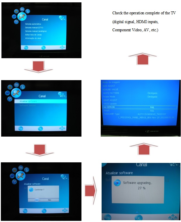
Firmware Upgrade
Note: Take the other models for example.
Attention˖
1. Prepare a U-disk, the file system of FAT is the best choice.
2. Change the “.pkg” software file name to “upgrade_loader.pkg” and copy it to U-disk root directory.
3. TV AC off, and insert the U-disk with F/W changed to the USB port of TV.
Note: Take the other models for example.
Attention˖
1. Prepare a U-disk, the file system of FAT is the best choice.
2. Change the “.pkg” software file name to “upgrade_loader.pkg” and copy it to U-disk root directory.
3. TV AC off, and insert the U-disk with F/W changed to the USB port of TV.
4.
After TV AC on, TV will detects the F/W in the U-disk to upgrade automatically.
During this process, it is forbid to
AC off TV and unplug the U-diskDŽ TV will restart after upgrade.
5. Unplug the U-disk and restart TV.
6. Press “menu+1999” by RC to open factory menu and check the software version as below figure. If the version information is not the same as the F/W in U-disk, please redo upgrade.
AC off TV and unplug the U-diskDŽ TV will restart after upgrade.
5. Unplug the U-disk and restart TV.
6. Press “menu+1999” by RC to open factory menu and check the software version as below figure. If the version information is not the same as the F/W in U-disk, please redo upgrade.
EDID Upgrade
(Take Philip_201T1 for example.)
1.
Ready for writing EDID

Install USB driver.
When insert the USB cable to PC USB port, will pop up a Hardware Wizard to help you install the USB driver if you use this ISP board first time. You can install it successfully as the below instruction step by step.
Remark: The USB driver files path: D:\FTC100103(Mstar)\FTCUSB.INF
When insert the USB cable to PC USB port, will pop up a Hardware Wizard to help you install the USB driver if you use this ISP board first time. You can install it successfully as the below instruction step by step.
Remark: The USB driver files path: D:\FTC100103(Mstar)\FTCUSB.INF
Install TPVedid tool.
1.
Run the “InstallEdidXP.bat” firstly by double-click it icon. And press any key
to finish it.
2.
Double-click “TpvEdid.exe” to open the EDID tool.
3.
Click “FPD” to open another interface.
4.
Click “Read File” to load the correct EDID file.
5.
After loading the VGA EDID file, AC on the TV and click “Test EDID” to check
the communication between TV and PC. When there is “edid write protected”
letters, we can click “Write EDID” to program.
6.
Click “Write EDID” to start writing.
7.
Click “Read EDID” to read the EDID information from TV.
8.
Click “Edid Content” to check whether the EDID read from TV is correct or not.
If the EDID information is the same as what you have written, EDID write
successfully.
Write HDMI EDID.
1 Connection for write HDMI1 EDID.
1 Connection for write HDMI1 EDID.
2.
For the other steps, please refer to the writing VGA EDID steps.
3. Write the EDID for other HDMI ports EDID one by one as the VGA EDID writing steps.
3. Write the EDID for other HDMI ports EDID one by one as the VGA EDID writing steps.